Vk series, General pump – General Pump VK Repair Manual User Manual
Page 9
GENERAL PUMP
A member of the Interpump Group
VK SERIES
Page 9
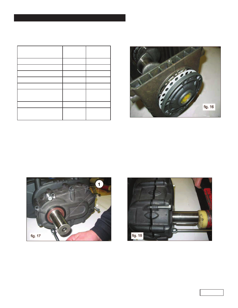
Determine the shim packs as indicated in the following table:
Insert the shims under the indicator side cover (fig. 16), fastening it to the cover with the respective screws,
checking that the resistant torque is between 3 Ft.lbs. (4 Nm) and 5 Ft.lbs. (7 Nm). If the torque is correct,
proceed with connecting the con-rods to the bend shaft. otherwise redefine the shims repeating the
operations.
2.1.5 Disassembling the Reduction Gear Unit
Remove the reduction gear box cover fixing screws. Position the holes and screw in 3 grub screws or M8
threaded screws (1, fig. 17) with the function of extractors and simultaneously tap on the pinion in such a way
that the bearing remains on during cover extraction (fig. 18).
Detected
Measurement
Shim
Type
# Pieces
From: 0.05 to: 0.10
/
/
From: 0.11 to: 0.20
0.1
1
From: 0.21 to: 0.30
0.1
.2
From: 0.31 to: 0.35
0.25
1
From: 0.36 to: 0.45
0.35
1
From: 0.46 to: 0.55
0.35
0.10
1
1
From: 0.56 to: 0 .60
0.25
2
From: 0.61 to: 0.70
0.35
0.25
1
1
- 47 Series (4 pages)
- 60 TC Series (4 pages)
- 66 Series HTF, TSF & TSP Crankshaft Flip (4 pages)
- 66 Series TSF (4 pages)
- 66 Series TSP (5 pages)
- 71 Series Gearbox (13 pages)
- HE (20 pages)
- HF Owner Manual (24 pages)
- HF Repair Manual (17 pages)
- HTCK3623S (19 pages)
- HTCK4050S (19 pages)
- KE Owner Manual (22 pages)
- KE Repair Manual (16 pages)
- KEZ Owner Manual v.1 (17 pages)
- KEZ Owner Manual v.2 (17 pages)
- KEZ Repair Manual (16 pages)
- KFM Owner Manual (17 pages)
- KFM Repair Manual (16 pages)
- KF Owner Manual (22 pages)
- KF Repair Manual (15 pages)
- KFZ Owner Manual (24 pages)
- KFZ Repair Manual (15 pages)
- KL (19 pages)
- KS Owner Manual (23 pages)
- KS Repair Manual (21 pages)
- T16A-18A-20A-22A (21 pages)
- T24A-26A-28A-30A-26A-40A (22 pages)
- KT (35 pages)
- LH (21 pages)
- LK Owner Manual (24 pages)
- LK Repair Manual (50 pages)
- MH (18 pages)
- MK Owner Manual (21 pages)
- MK Repair Manual (45 pages)
- MKS Owner Manual (21 pages)
- MKS Repair Manual (45 pages)
- MS Owner Manual (20 pages)
- MS Hydraulic Drive Owner Manual (2 pages)
- MSS Owner Manual (21 pages)
- MW Owners Manual (34 pages)
- MW Repair Manual (54 pages)
- Pump Installation and Service Manual (12 pages)
- SH (18 pages)
- SK Owner Manual (22 pages)
- SK Repair Manual (44 pages)