Vk series – General Pump VK Repair Manual User Manual
Page 4
GENERAL PUMP
A member of the Interpump Group
VK SERIES
Page 4
2.1.1 Disassembly of Mechanical Parts
The correct sequence is the following:
• The pump shaft tab
• The rear cover
• The connecting rod cap
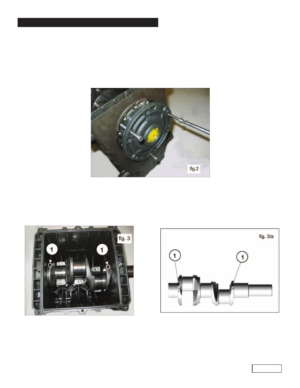
• The side covers using for extraction 3 fully threaded M6x50 screws, inserting them
in the threaded holes as indicated in fig. 2.
Push the plunger guides forward with their con-rods to facilitate side extraction of the pump. there are two
reference points visible on the shaft, 1, as shown in fig. 3 and in fig. 3a. These must be turned toward the
operator to facilitate extraction.
Note: Extraction of the plunger guides depends on prior removal the ceramic plunger and the relative spray
hood.
• Disassemble the con-rod units:
1. Unscrew the con-rod cap fixing screws.
2. Extract the con-rod caps with their relative semi-bearings (fig. 4), taking special care of the
disassembly sequence during disassembly.
To avoid possible errors, caps and con-rod shanks have been numbered on one side (1, fig. 4a).
- 47 Series (4 pages)
- 60 TC Series (4 pages)
- 66 Series HTF, TSF & TSP Crankshaft Flip (4 pages)
- 66 Series TSF (4 pages)
- 66 Series TSP (5 pages)
- 71 Series Gearbox (13 pages)
- HE (20 pages)
- HF Owner Manual (24 pages)
- HF Repair Manual (17 pages)
- HTCK3623S (19 pages)
- HTCK4050S (19 pages)
- KE Owner Manual (22 pages)
- KE Repair Manual (16 pages)
- KEZ Owner Manual v.1 (17 pages)
- KEZ Owner Manual v.2 (17 pages)
- KEZ Repair Manual (16 pages)
- KFM Owner Manual (17 pages)
- KFM Repair Manual (16 pages)
- KF Owner Manual (22 pages)
- KF Repair Manual (15 pages)
- KFZ Owner Manual (24 pages)
- KFZ Repair Manual (15 pages)
- KL (19 pages)
- KS Owner Manual (23 pages)
- KS Repair Manual (21 pages)
- T16A-18A-20A-22A (21 pages)
- T24A-26A-28A-30A-26A-40A (22 pages)
- KT (35 pages)
- LH (21 pages)
- LK Owner Manual (24 pages)
- LK Repair Manual (50 pages)
- MH (18 pages)
- MK Owner Manual (21 pages)
- MK Repair Manual (45 pages)
- MKS Owner Manual (21 pages)
- MKS Repair Manual (45 pages)
- MS Owner Manual (20 pages)
- MS Hydraulic Drive Owner Manual (2 pages)
- MSS Owner Manual (21 pages)
- MW Owners Manual (34 pages)
- MW Repair Manual (54 pages)
- Pump Installation and Service Manual (12 pages)
- SH (18 pages)
- SK Owner Manual (22 pages)
- SK Repair Manual (44 pages)