Ak/av parts drawing – Finish Thompson AK / AV 4 & 5 SERIES User Manual
Page 2
2
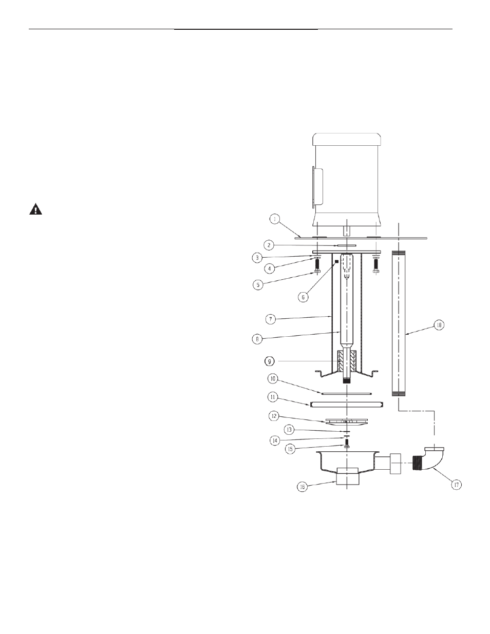
Figure 2
PiPiNG to AND from the PumP:
Always support the piping near the pump to minimize stress
and strain.
minimize frictional losses by increasing the piping size by one
diameter.
use a minimum number of bends, keeping any bends a mini-
mum distance of ten pipe diameters from the pump.
install a valve on the discharge line to control the flow. Place
the valve within a distance of ten pipe diameters from the
pump.
ensure that the pump is leak free.
maintain a flooded suction at all times. use a float switch to turn
off the pump at low level.
CAutIon: suction prime must be maintained at all times.
Running the pump dry will cause damage to the pump
components. to protect the pump if prime is lost, use a
pressure switch on the discharge or a motor power monitor
to monitor motor current draw.
note: AK4 & AK5 can be run dry without damage since they have no
lower bushing.
eleCtRICAl ConneCtIons:
1. Perform the motor wiring according to NeC requirements and
local electrical codes.
2. wire the motor for clockwise rotation when facing the fan end
of the motor.
3. to verify correct motor rotation:
a. install the pump into the system.
b. fully open the suction and the discharge valves.
c. Allow fluid to flow into the pump. Do not allow the pump
to run dry, as this will cause damage to pump components.
d. Jog the motor (allow it to run for only one to two seconds)
and observe the rotation of the motor fan. refer to the
directional arrow on the pump if needed.
note:
A pump running backwards will pump, but a greatly reduced
flow and pressure.
opeRAtIon
1. Partially open the discharge valves.
2. start the pump and verify liquid is flowing. if there is no liquid
flow, refer to the “troubleshooting” section of these instruc-
tions.
3. Adjust the flow rate and pressure by regulating the discharge
valve.
AK/AV Parts Drawing