Finish Thompson MSVKC Series User Manual
Page 2
23
1. Unpack the pump parts and any supplied accessories and examine
for damage. If damage is detected, save the packaging and notify
the carrier immediately.
2. Prepare to assemble the pump onto the motor by placing the motor
on the fan cover on a suitable clean, level work surface.
3. Install the keyway into motor shaft key slot. Align the keyway slot in
flywheel adapter / coupling half combination (item 34 and metal half
of item 29 in figure 5) and install on motor shaft with splined side
facing the pump. Note: these items are pre-assembled at the factory.
Set coupling half flush with the end of the motor shaft and secure with
coupling support washer, lock washer and bolt (items 38B, 39 & 40
in figure 5). Tighten both setscrews in coupling half with 1/8” Allen
wrench to 7.9 N-m.
4. Install the metric motor adapter (item 2 in figure 5) onto the motor. To
aid in correct installation, the letters “A” and “B” are molded on the
opposite sides of the metric motor adapter. For 80 frame motors using
the correct hardware (items 3,4 and 5 in figure 5) mount the adapter
with side “A” facing up. The metric motor adapter must be positioned
so that the adapter seats onto the motor rabbet. See figures A & B
above.
Caution: Improper positioning of the metric motor adapter can
cause premature coupling failure or cause the pump shaft to bottom
out before the pump is properly installed onto the motor adapter.
5. Install the flywheel (item 35 in figure 5) onto the flywheel adapter and
attach using four screws with lock washers (items 36 and 37 in figure
5). Tighten securely.
6. Insert the coupling insert (yellow internally splined plastic sleeve) into
the coupling half on the motor. Carefully slide the motor adapter end
(item 9 in figure 5) of the pump assembly over the motor shaft until
both coupling halves are completely seated in the coupling insert.
Make sure rabbet on the motor is firmly seated into the motor adapter.
7. Rotate the pump discharge and mounting plate if ordered to the desired
orientation. Align the bolt holes on the mounting plate with the motor
adapter (item 9) and the metric motor adapter flange (item 2). Secure
with the hardware provided.
8. Make sure that the locking rings are securely snapped in place and
did not loosen during shipping or the assembly process.
Caution: Pump assembly may be top heavy.
Install the pump into the system according to the installation instructions
provided.
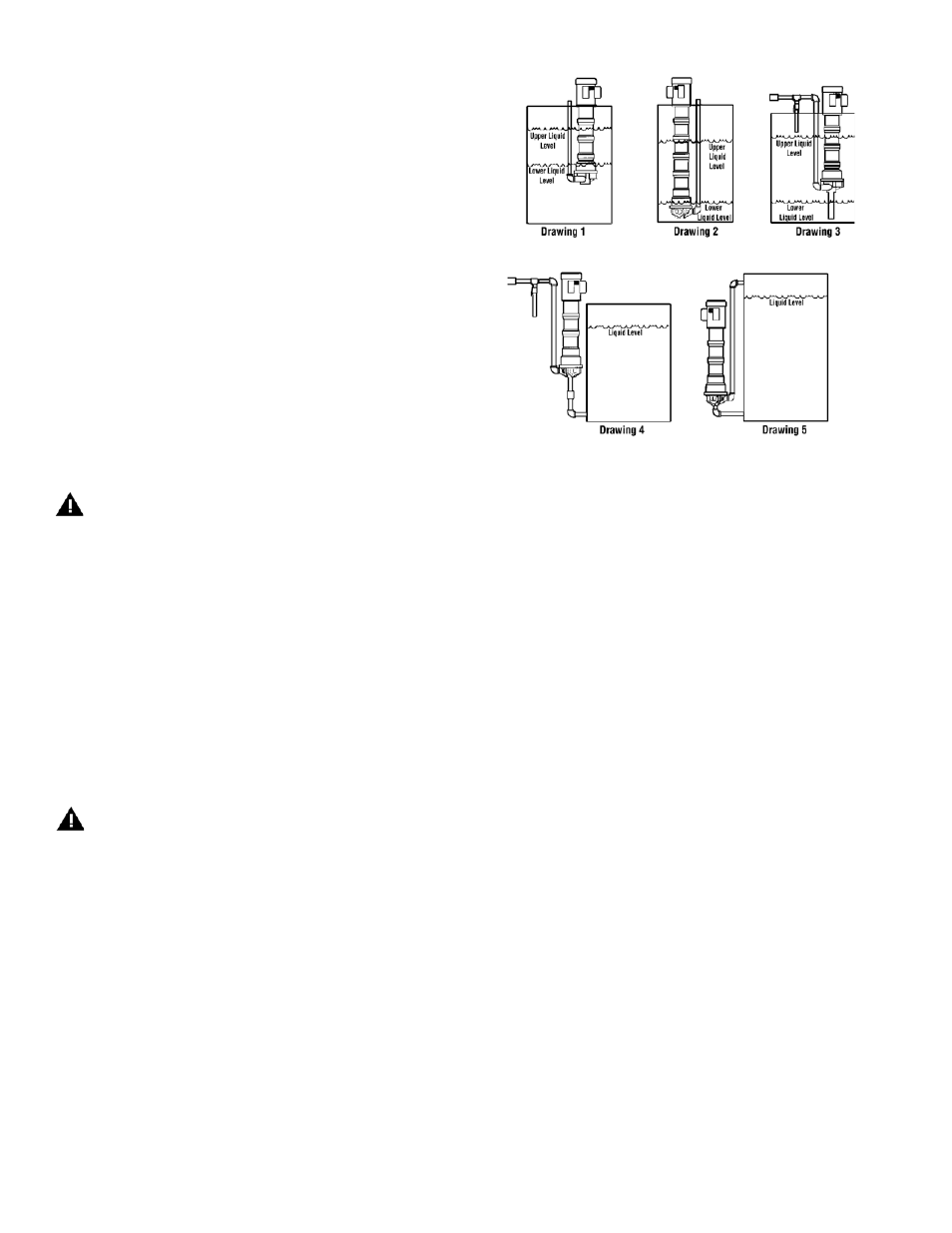
Drawing 1 shows drawing of pump mounted inside a tank with suction off the bottom of the tank
and level fluctuating from near top of pump column to close to the bottom of the pump.
Drawing 2 shows drawing of pump suction near tank bottom and level fluctuating between the
top and bottom of the tank.
Drawing 3 shows drawing of pump with suction extension and the level fluctuating between
startup level and low level.
Drawing 4 shows drawing of pump mounted outside the tank.
Drawing 5 shows drawing of pump mounted outside the tank with the motor below the liquid level.
mouNtiNg
A mounting plate is recommended for in-tank installations. Use a hole
saw to cut holes in desired location for piping if required.
Support and securely fasten the mounting plate on all four sides if
possible or on two sides if mounted in a corner. Drill holes in the
mounting plate at the desired location for bolting to the tank.
A drip cover may be installed on top of the motor if desired.
Mount pump in desired configuration. Securely fasten mounting
plate if used. Motor feet may also be used for mounting.
1. Support piping near the pump to eliminate any strain on the pump
casings. Do not use suction or discharge piping to support the pump.
2. Do not overtighten the piping on the discharge on initial installation
(i.e., down to the O-ring). Damage to the discharge can occur. The
O-ring is used only when there is wear and the plastic threads are
loose.
3. Do not place the pump suction directly on the bottom of the tank. Keep
the pump suction at least one pipe diameter off the bottom.
4. A suction extension tube of up to nine feet in length can be added.
5. To minimize head loss from friction:
a. Increase pipe size by 1 diameter.
b. Use minimal number of pipe bends.
6. If a check valve is installed in the discharge piping, an air bleed must
be installed in the discharge line to prevent air lock. This allows air
trapped in the pump internals to be removed on initial startup. See
Figure 1
drawings 3 and 4 in Figure 1.
PiPiNg
8. Install the pump into the system according to the installation instruc-
tions provided.
For 80 Frame metriC motor adaPter with Flywheel (item 35
iN Figure 5):
installation
The VKC Series is a versatile pump designed to be operated in a variety
of mounting configurations. The pump can be mounted either inside or
outside of a tank or sump. See Figure 1.
note: Drawings for illustration only. Pumps need to be properly sup-
ported when installed.