Safety precautions for atex pumps, Temperature classification, Bushing and thrust ring replacement – Finish Thompson KC22/32 SERIES User Manual
Page 3
3
SAFETY PRECAUTIONS FOR ATEX PUMPS
CAUTION: Proper o‑ring material must be chosen for the fluid being
pumped. Improper material selection could lead to swelling and be a possible
source of leaks. This is the responsibility of the end user.
WARNING: The pump must be checked for leaks on a regular basis. If
leaks are noticed, the pump must be repaired or replaced immediately.
WARNING: The pump must be cleaned on a regular basis to avoid dust
buildup greater than 5 mm.
WARNING: ATEX pumps must use a power monitor, flow switch, pressure
switch or similar device to help protect against dry running, closed discharge
valve and decoupling. Any of these conditions could lead to a rise in surface
temperature of the pump.
TEMPERATURE CLASSIFICATION
The surface temperatures of the KC ATEX Series pumps depend
upon the temperature of the fluid being pumped. The chart below
lists different fluid temperatures and the corresponding pump
surface temperatures.
Maximum
Allowable
Fluid
Surface Temperature Surface
Temperature Temperature Class Temperature
80
o
F (27
o
C) 122
o
F (50
o
C) T6
85
o
C
185
o
F (85
o
C) 192
o
F (89
o
C) T4
135
o
C
220
o
F (104
o
C) 248
o
F (120
o
C) T3
200
o
C
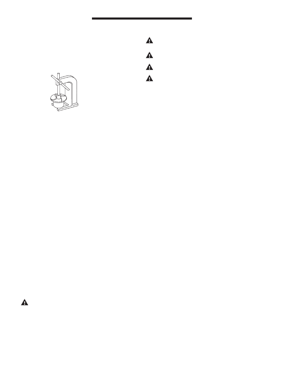
Figure 6
Note: On closed impellers, use two screwdrivers in slots provided to pry
apart impeller and impeller drive.
BUSHING AND THRUST RING REPLACEMENT
1. To remove the bushing, place the impeller assembly (items
2 and 3) in an arbor press. Insert a 1" diameter plastic or
wooden shaft through the impeller and press bushing out.
Refer to Figure 6.
2. To replace bushing, place the impeller assembly (items
2 and 3) on a flat surface with the thrust ring face down
(item 2A). Insert the bushing (item 3A), slotted face out,
into impeller assembly. Gently push until bushing bottoms
out. Bushing should be flush with impeller eye.
3. Impeller thrust ring (item 2A) can be removed from impel‑
ler body (item 2) by gently pulling ring from impeller nose.
Note: The thrust ring on the closed impeller must be
removed by grasping with a pliers and twisting. Once
removed, a new thrust ring is required.
4. To replace thrust ring, align ring (grooved side up) with
the inside of the impeller assembly (item 2), and press into
place.
Note: Protect face with wood or plastic and avoid tilting
ring.
REASSEMBLY
1. Insert impeller assembly (items 2 and 3) into barrier (item
4). Make sure impeller is free of metal chips. Install new
O‑ring (item 13) onto lip of barrier (item 4).
2. Install impeller housing (item 1 ) onto barrier (item 4). In‑
sert 2 housing studs and washers (items 15 &16) long end
into back of barrier (item 4) and push through the impeller
housing (item 1) until threads are exposed. Install nut and
washer (items 8 & 9) and tighten. On the other end of the
stud you will find a threaded housing nut (item 16). This
nut can be tightened using a pliers or crescent wrench. It
is important to leave about 3/4" of thread exposed so nuts
and washers can be installed on motor adapter side.
3. Complete reassembly following steps 5, 6, 7 and 8 of
“Pumps Without Motors” section on page 1 of these
instructions.
CAUTION: If item numbers 14, 9 and 8 are removed from
the motor adapter (item 6), it is very important to place a
small amount of “Loc‑Tite” removable thread locker‑242
onto the threads of the socket head cap screw (item 14)
before installing back into the nut (item 8). The above pro‑
cedure is only necessary for the U.S. adapters 184 TC and
213 TC and prevents the parts from working loose during
normal operation. Failure to comply may cause damage to
the pump!