Maintenance, Operation – Finish Thompson KC22/32 SERIES User Manual
Page 2
2
3. Connect drain hose to water outlet valve.
4. Open inlet and outlet valves, and flush system until pump
is clean (approximately 5 minutes).
MAINTENANCE
DISASSEMBLY
1. Disconnect power. Remove electrical wiring and mounting
bolts to floor or base plate.
2. Close suction and discharge valves, and disconnect piping.
3. Remove bolts, nuts and washers (items 7, 8 and 9). Leave
the 2 housing studs (item 15) in place until the wet end is
removed.
4. Securely clamp or hold motor in place. Remove wet end
assembly by inserting both thumbs into pump suction and
pulling assembly straight out with a quick motion.
WARNING: Components can slam together from strong
magnets. Keep fingers away from area between housing
and motor adapter.
5. Disassemble wet end by removing 2 housing studs and
nuts (items 16) which attach barrier (item 4) to impeller
housing (item 1). Remove and discard o‑ring (item 13).
6. Remove drive magnet assembly by inserting a 3/16" hex
wrench into access hole in side of motor adapter and
loosening 2 set screws (item 5A). Grasp inside of magnet
assembly and pull off of motor shaft.
CAUTION: Strong magnets present. Keep metal objects and
metallic chips/particles away from pump components.
EXAMINATION
1. Check impeller drive bushing (item 3A) and impeller thrust
washer (item 2A). If cracked, chipped or scored, then
replace. Replace if minimum groove height is less than the
minimum height recommended. See Figure 4.
2. Check for loose magnets.
ELECTRICAL
Install motor according to NEC requirements and local electrical
codes.
IMPORTANT: To verify correct motor rotation: (1) Install pump into system.
(2) Fully open suction and discharge valves. (3) Allow fluid to flow into the
pump. Do not allow pump to run dry (PTFE and ceramic bushings cannot be
run dry without damage to pump components). (4) Jog motor (allow it to run
for one or two seconds) and observe rotation of motor fan. Correct rotation is
clockwise as viewed from motor fan. Refer to directional arrow on pump.
OPERATION
START UP
1. This pump must be filled from a flooded suction tank
(gravity) or primed with liquid from an outside source. The
KC22/32 are not self‑priming.
2. Open the inlet (suction) and discharge valves completely
and allow the pump to fill with liquid.
3. Close the discharge valve.
4. Turn the pump on. Slowly open the discharge valve. Adjust
the flow rate and pressure by regulating the discharge
valve. Do not attempt to adjust the flow with the suction
valve.
5. Use of a power monitor is strongly recommended for
pumps with ceramic, PTFE or silicon carbide bushings.
The power monitor will stop the pump and help prevent
damage should the pump run dry. ATEX certified pumps
MUST use a power monitor.
SHUT DOWN
Use the following procedure to shutdown the pump.
1. Slowly close the discharge valve.
2. Turn off the motor.
3. Close the suction valve.
FLUSH SYSTEM
1. Fully close suction and discharge valves.
2. Connect water supply to water inlet valve.
9. The suction valve should be fully open to avoid restricting
suction flow.
IMPORTANT: To protect the pump if prime is lost, use one
of the following: (1 ) pressure switch on the discharge;
(2) vacuum switch on the suction; (3) a power monitor to
monitor motor current.
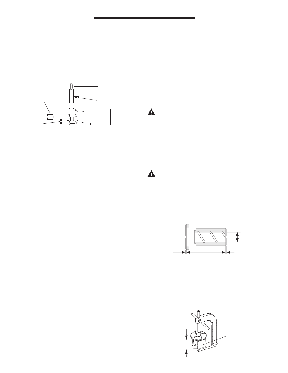
10. When pumping liquids which may solidify or crystallize, a
flush system should be added to the piping. See Figure 3.
Install water inlet and outlet valves as shown.
Discharge
Valve
Water Inlet
Valve
Suction
Valve
Water Outlet
Valve
Figure 3
.780 MAX.
Diameter
.020 MIN.
Groove Height
Figure 4
IMPELLER DISASSEMBLY
1. To separate impeller body (item 2) from the impeller drive
(item 3), support the body in an arbor press using two 5"
minimum spacer blocks.
2. Insert a 1‑1/2" diameter plastic or wooden shaft into the
impeller eye, and push the drive out of the body. See
Figure 5.
Figure 5
5” MIN.
Support