Safety precautions for atex pumps, Reassembly, Troubleshooting – Finish Thompson KC11 SERIES User Manual
Page 3
3
CAUTION: Proper o-ring material must be chosen based on
the fl uid being pumped. Improper material selection could lead to
swelling and a possible source of leaks. This is the responsibility of
the end user.
WARNING: ATEX pumps must use a power monitor, fl ow
switch, pressure switch or similar device to help protect against dry
running, closed discharge valve and decoupling. Any of these condi-
tions could lead to a rise in surface temperature of the pump.
TEMPERATURE CLASSIFICATION
The surface temperatures of the KC ATEX Series pumps depend
upon the temperature of the fl uid being pumped. The chart below
lists different fl uid temperatures and the corresponding pump
surface temperatures.
Maximum
Maximum
Allowable
3. Lubricate the o-ring with a chemically compatible lubricant and
install impeller housing (item 1) onto barrier, making sure to align
matching bosses on barrier with recesses in impeller housing.
Install 4 Phillips head screws and tighten carefully, do not over-
tighten.
4. For reassembly of wet end to motor, refer to assembly section,
page 1, steps 6- 8.
SAFETY PRECAUTIONS FOR ATEX PUMPS
WARNING: The pump must be checked for leaks on a regular
basis. If leaks are noticed, the pump must be repaired or replaced
immediately.
WARNING: The pump must be cleaned on a regular basis to
avoid dust build up greater than 5 mm.
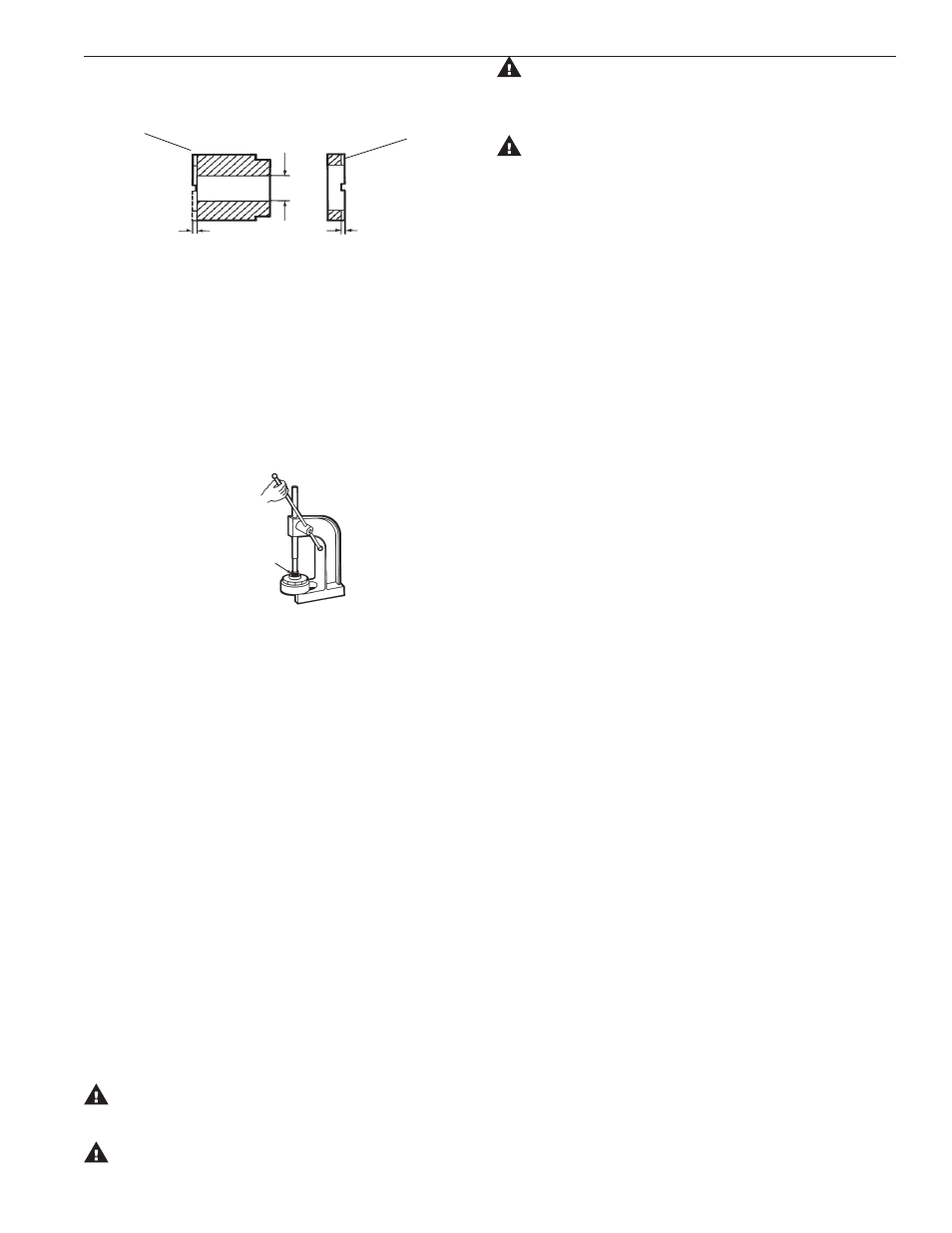
Figure 5
.020 MIN.
Groove
Height
(Item 2A)
Carbon
.020 MIN.
Groove
Height
.515" Max. Dia.
Front Face
Bushing
(Item 2B)
Tefl on
Thrust Ring
Figure 4
BUSHING AND THRUST RING REPLACEMENT
1. To remove the bushing, place the impeller assembly (item 2)
in an arbor press. Insert a 3/4" diameter plastic or wood shaft
through the eye of the impeller and press bushing out. Refer to
Figure 5.
2. To replace the bushing, place the top of the impeller on an arbor
press with the thrust ring (item 2B) face down. Insert the front of
the bushing (see fi gure 4) into the center of the impeller, aligning
the fl at on the bushing with the fl at in the impeller. Press into
place until the rear of the bushing (the slotted end) is .855 below
the bottom of the impeller. An installation tool (P/N M102392)
is available to aid in proper installation.
3. The impeller thrust ring (item #2B) can be removed from the im-
peller body (item #2) by gently pulling the ring from the impeller
cover.
4. To replace the thrust ring, align the fl at on the ring (grooved side
up) with the fl at on inside of the impeller assembly (item 2), and
press into place.
Note: Protect thrust ring face with wood or plastic and avoid tilting
of the ring.
REASSEMBLY
WET END SUBASSEMBLY
1. Install o-ring (item 6) onto lip of barrier assembly (item 3).
2. Make sure impeller assembly is free of metal chips. Position
impeller assembly (item 2) onto shaft and lower into barrier.
Fluid Surface
Temperature
Surface
Temperature Temperature Class Temperature
80
o
F (27
o
C) 122
o
F (50
o
C) T6
85
o
C
185
o
F (85
o
C) 192
o
F (89
o
C) T4
135
o
C
220
o
F (104
o
C) 248
o
F (120
o
C) T3
200
o
C
TROUBLESHOOTING
NO DISCHARGE
1. Pump not primed.
2. Discharge head too high.
3. Suction lift too high. Insuffi cient NPSH.
4. Closed
valve.
5. Viscosity too high (magnets uncoupled).
INSUFFICIENT DISCHARGE
1. Air leaks in suction piping.
2. Discharge head higher than anticipated.
3. Suction lift too high or insuffi cient NPSH. Check also for
clogged suction line or foot valve.
4. Foot valve too small.
5. Foot valve or suction opening not submerged enough.
INSUFFICIENT PRESSURE
1. Air or gasses in liquid.
2. Impeller diameter too small.
3. Discharge head higher than anticipated.
LEAK AT IMPELLER HOUSING
1. O-ring pinched or chemically attacked. Replace with new o-ring.
2. Phillips pan head screws improperly or overtightened. Install
according to assembly instructions.
3. Check motor adapter for cracks.
4. Total overall pressure too high. Do not exceed 35 psi inlet and
outlet pressure.
LOSS OF PRIME
1. Leaking suction line.
2. Suction lift too high or insuffi cient NPSH.
3. Air or gasses in liquid.
4. Foreign matter in impeller.
5. Leaking foot valve.
TROUBLESHOOTING continued on page 5.