Finish Thompson KC 5.5, 6, 6H, 7, 8, & 10 SERIES User Manual
Page 2
3
2
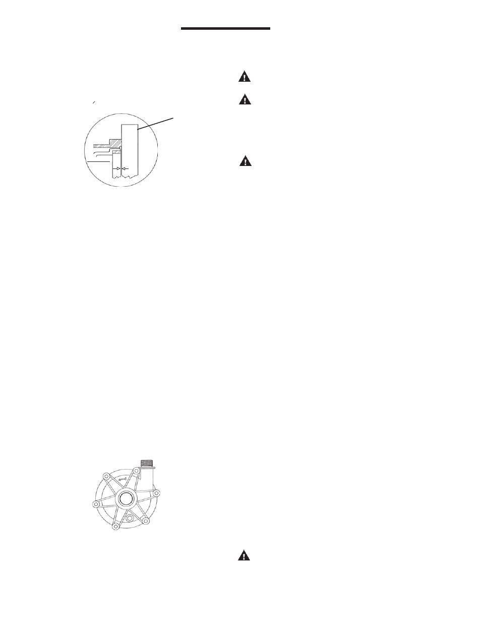
For 71 and 80 frame - Align the cone point set screw (item
6B) on the motor shaft and slide the drive magnet assembly
(item 6) onto the motor shaft. Adjust the drive so that it is
1.016 mm (.040 + or -.005) below the face of the motor
adapter (see figure 2). Tighten both setscrews with a 5/32”
Allen wrench to 7.9 N-m (70 in-lbs.).
6. Place the impeller assembly (comprised of items 2 and 3) in
barrier (item 4). Grasping the barrier at opposite bolt tabs,
carefully lower the barrier assembly into the motor adapter/
drive assembly. Line up the tabs of the barrier between the
tabs on the motor adapter to avoid pinching fingers. Once
seated, rotate the barrier until bolt holes line up.
7. Install the o-ring (item 7) on the barrier. Lubricate the o-ring
with a compatible lubricant to facilitate installation.
8. Place the impeller housing (item 1) on the barrier being
careful not to dislodge the o-ring.
9. Align mounting holes and install 6 mounting screws and
washers (items 9A, 9B & 9C) from hardware package. Hand-
tighten screws using pattern shown in Figure 3.
Manually rotate the pump assembly to ensure that the pump
is not binding or rubbing on the drive magnet assembly.
INSTALLATION
MOUNTING
Motor should be securely fastened.
PIPING
Figure 3
.
Figure 2
6
1
2
3
4
5
Note: Prior to start-up, double check the two set screws to as-
sure that they are firmly tightened. Failure to do so could result
in internal damage. Rotate to assure clearance with the motor
adapter.
WARNING: Magnets are strong. To avoid damage and
pinching fingers, tightly grasp pump assembly keeping
finger tips away from the area where the housing and
motor adapter meet.
CAUTION: Do not operate/test the motor with the drive magnet
assembly exposed.
CAUTION: Drive magnets MUST be free of metal chips.
10. Install pump into the system according to installation
instructions.
1. Support piping near the pump to eliminate any strain on
the pump casings.
2. Do not overtighten the piping on the discharge on initial
installation (i.e., down to the o-ring). Damage to the
discharge can occur. The o-ring is used only when there
is wear and the plastic threads are loose.
3. To minimize head loss from friction:
a. Increase pipe size by 1 diameter.
b. Use minimal number of pipe bends.
4. Keep bends and valves a minimum of 10 pipe diameters from
the suction and discharge.
5. Position pump as close to the liquid source as possible.
6. Maintain a flooded suction (liquid above pump prior to
being primed).
7. Ensure that the piping does not leak and suction is not
prone to clogging.
8. If flexible hose is preferred, use a reinforced hose rated for the
proper temperature and pressure. This helps avoid collapse or
kinks.
9. Install valves on suction and discharge lines (a minimum of 10
pipe diameters from the pump).
10. For units in a suction lift system, install appropriate piping in
the discharge to allow priming of the pump.
11. The suction valve should be completely open to avoid
restricting suction flow.
CAUTION: To stop the pump if prime is lost, use one of the
following: (1) pressure switch on the discharge, (2) vacuum
switch on the suction, (3) a motor minder to monitor motor
current.
with the key slot on the shaft adapter and slide the drive
magnet assembly (item 6) on. Adjust the drive magnet
assembly (item 6) so that it is 1.016 mm (.040 +/- .005)
below the face of the motor adapter (see figure 2) and
tighten both setscrews with a 5/32” Allen wrench to 7.9 N.m
(70 in. lbs.).
S
TRAIGHT
EDGE
DRIVE
MAGNET
ASSY
.
.040