Finish Thompson DB6, 6H, 7, 8, 9, 10 Series User Manual
Page 8
Flush Systems
CAUTION: Some fluids react with water; use compatible flushing
fluid.
1. Turn off the pump.
2. Completely close the suction and discharge valves
3. Connect flushing fluid supply to flush inlet valve.
4. Connect flushing fluid drain to flush drain valve.
5. Open flushing inlet and outlet valves. Flush system until the pump
is clean.
Optional Drain Installation
1. Remove the impeller housing (item 1) from the pump assembly.
2. Clamp the impeller housing to a drill press table.
3. Using a 7/16” drill and the molded boss as a guide, drill com-
pletely through the molded boss into the interior of the impeller
housing.
CAUTION: Do not tap too deep or the impeller housing may be
damaged.
4. Using a ¼” NPT tap, tap the hole in the molded boss to the ap-
propriate depth.
5. Install the drain plug or valve, being careful not to over-tighten.
Section IV - Maintenance
Recommended maintenance schedule
The recommended maintenance schedule depends upon the nature
of the fluid being pumped and the specific application. If the pump is
used on a clean fluid, it is recommended that the pump be removed
from service and examined after six months of operation or after 2,000
hours of operation. If the pump is used on fluids with solids, high tem-
peratures or other items that could cause accelerated wear, then this
initial examination should be sooner.
After the initial examination of the internal components and wear items
are measured, a specific maintenance schedule can be determined.
For best results, it is recommended that the pump be removed from
service annually for examination.
Section V - Disassembly
WARNING: Rotating Parts. This pump has components that rotate
while in operation. Follow local safety standards for locking out the
motor from the power supply during maintenance or service.
WARNING: Chemical Hazard. This pump is used for transferring
many types of potentially dangerous chemicals. Always wear protective
clothing, eye protection and follow standard safety procedures when
handling corrosive or personally harmful materials. Proper procedures
should be followed for draining and decontaminating the pump before
disassembly and inspection of the pump. There may be small quanti-
ties of chemicals present during inspection.
WARNING: Magnetic force hazard. This pump should only be dis-
assembled and assembled using the recommended procedures. The
magnetic attraction is powerful enough to rapidly pull the motor end
and the wet end together. Do not place fingers between the mating
surfaces of the motor and wet ends to avoid injuries. Keep the drive
magnet and impeller assembly away from metal chips or particles.
1. Stop the pump, lock out the motor starter, close all the valves that
are connected to the pump, and drain/decontaminate the pump.
WARNING: The pump must be thoroughly flushed of any haz-
ardous materials and all internal pressure relieved prior to opening
the pump. Allow the pump to reach ambient temperatures prior to
performing maintenance.
2. Securely clamp the motor to the bench. Remove the (4) bolts, lock
washers and flat washers (items 24, 25, 26) securing the pump to
the motor.
3. Firmly grab the pump and pull straight
back to disengage the motor and the
pump. See figure 10.
4. Place pump on bench with housing
facing up. Remove (6) 8 mm hous -
ing bolts, lock washers and flat
washers (items 15, 16, 17). See
figure 11.
5. Pull housing (item 1) straight up to
remove. Inspect housing for signs of
wear or damage. Look for signs of
rubbing, cracked thrust ring or dam-
age to front shaft support. See
figure 12.
6. Remove impeller/inner drive assembly
(items 4A, 4, 5, 5A). Inspect impeller
and drive for signs of wear or damage.
Look for signs of rubbing, damage and
wear to the impeller and inner drive.
See figure 13.
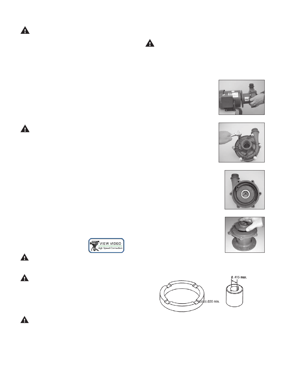
Check the impeller thrust ring and
bushing for wear. See figure 14.
5
Figure 10
Figure 11
Figure 12
Figure 13
Figure 14