Finish Thompson DB6, 6H, 7, 8, 9, 10 Series User Manual
Page 5
WARNING: The pump and associated components are heavy. Failure to properly support the pump during lifting and movement could result
in serious injury or damage to the pump and components.
WARNING: Never run pump at less than minimum flow or with the discharge valve closed. This could lead to pump failure.
Installation/Operation Precautions
CAUTION: This pump should never be operated without liquid in the casing. It is recommended that run dry protection be used. Optional
electronic power monitors are available to help protect against run dry. If the pump has a PTFE, ceramic or silicon carbide bushing, IT CANNOT BE
RUN DRY WITHOUT CAUSING DAMAGE TO THE PUMP. However, the pump can operate without liquid in the casing if the pump has a carbon bush-
ing. The exact length of time the pump can operate dry with a carbon bushing varies with operating conditions and the environment.
CAUTION: Never start or operate with a closed suction valve. Never operate with a closed discharge valve.
CAUTION: Always provide adequate NPSHa (net positive suction head available). It is recommended to provide at least 2 feet (61 cm) above
the NPSHr (net positive suction head required).
CAUTION: If pump is used on variable speed drive, do not exceed the frequency for which the pump was designed (for example, if the pump
is a 50 Hz model, do not exceed 50 Hz).
Safety Precautions for ATEX Pumps
CAUTION: Proper o-ring material must be chosen for the fluid being pumped. Improper material selection could lead to swelling and be a
possible source of leaks. This is the responsibility of the end user.
WARNING: The pump must be checked for leaks on a regular basis. If leaks are noticed, the pump must be repaired or replaced immediately.
WARNING: The pump must be cleaned on a regular basis to avoid dust buildup greater than 5 mm.
WARNING: ATEX pumps must use a power monitor, flow switch, pressure switch or similar device to help protect against running dry, closed
discharge valve and decoupling. Any of these conditions could lead to a rise in surface temperature of the pump.
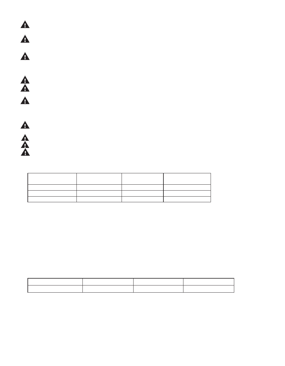
Temperature Classification
Fluid Temperature
Maximum Surface
Temperature
Temperature Class
Maximum Allowable
Surface Temperature
90º F (32º C)
125º F (52º C)
T6
85º C
180º F (82º C)
174 º F (81º C)
T4
135º C
220º F (104º C)
200º F (93º C)
T4
135º C
DB6, 6H, 7, 8, 9,10 Capabilities
• Maximum Working Pressure: 80 psi (5.5 bar)
• Maximum Viscosity:
150 cP
• Maximum Temperature: Polypropylene -180º F (82º C); PVDF – 220º F (104º C)
Note:
Maximum temperature is application dependent. Consult a chemical resistance guide or the chemical manufacturer for chemical
compatibility and temperature limits.
• Solids: Maximum particle size is 100 microns for slurries and 1/64” (.4 mm) for infrequent particles. Maximum hardness is 80 HS. Maximum
concentration is 10% by weight. If solids are being pumped, it is recommended that the pump have either ceramic or for best results, silicon
carbide components. Pumping solids may lead to increased wear.
Minimum Allowable Flow Rate
Do not allow the flow rate to drop below the minimum flow rate listed in the chart below.
3450 rpm
1725 rpm
2900 rpm
1450 rpm
1/2 gpm (1.9 lpm)
1/4 gpm (.95 lpm)
1.9 lpm (1/2 gpm)
.95 lpm (1/4 gpm)
Maximum Allowable Motor Power
Do not exceed the maximum power rating for the pump coupling. Standard coupling for the DB6, 6H & 7 is 6-pole; standard coupling for the
DB8, 9 & 10 is 8-pole.
· 6-pole coupling = 1/2 horsepower (0.37 kW)
· 8-pole coupling = 1 horsepower (0.75 kW)
· 10-pole coupling = 2 horsepower (1.50 kW)
2
Maximum Noise Level
69 dBA (Pump only)