Interconnection wiring, Dip (address) switch setup, sscs, Intalogix – Fairbanks MATRIX SCALE HIGHWAY SCALE SYSTEM User Manual
Page 27: Systems installation, continued, Always off
Section 4: Wiring
11/12
27
51182 Rev. 2
Intalogix
™
Systems Installation, Continued
Load Cell Wiring Designations
Color
Description
Black
(
─) Excitation
Green
(+) Excitation
Red
(
─) Signal
White
(+) Signal
Yellow
Shield
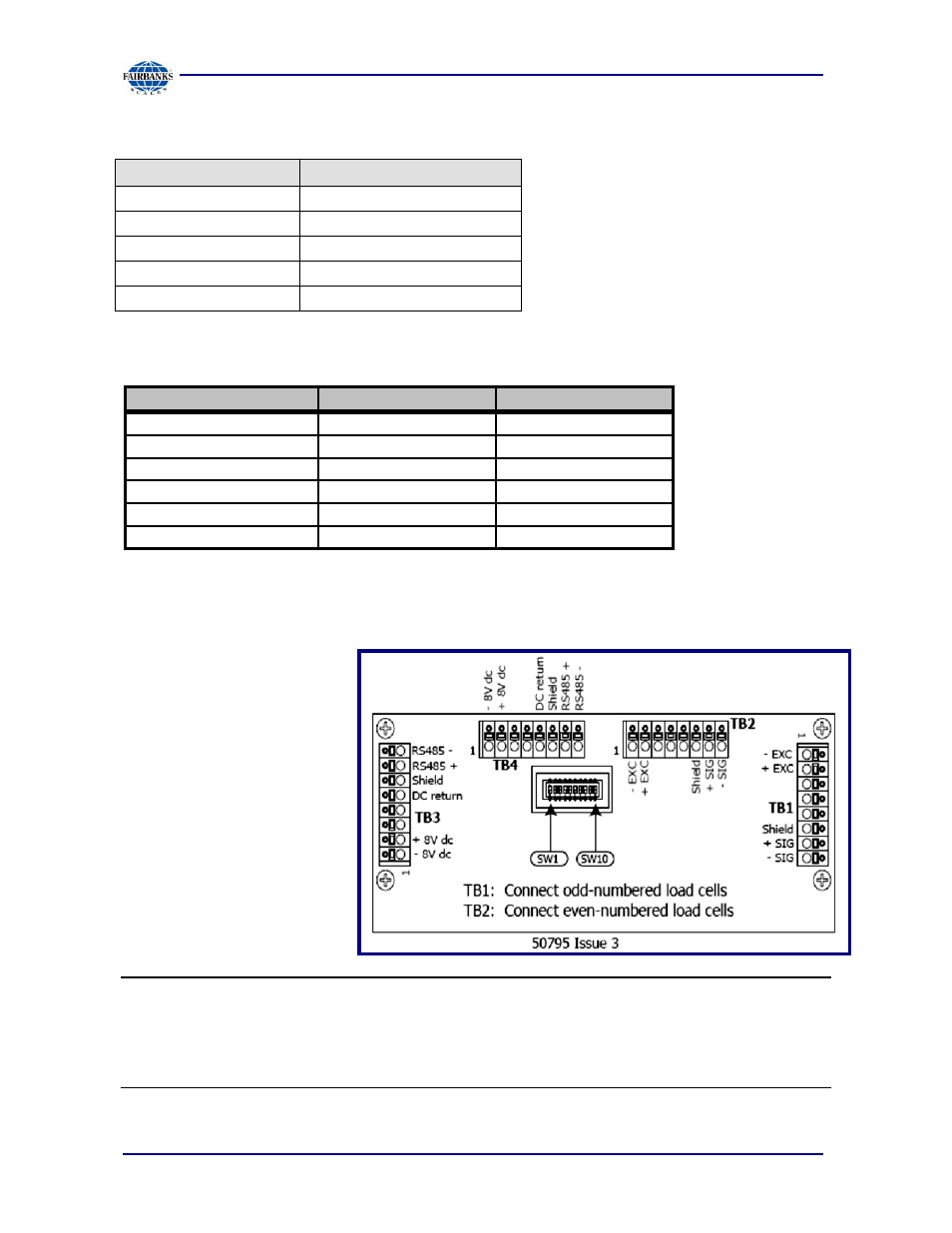
Interconnection Wiring
TB3 or TB4 in SSC
Function
17246 Cable
1
(-) 8.0 volts
Black
2
(+) 8.0 volts
Green
5
DC Return
Blue
6
Shield
Shield
7
RS-485 (+)
White
8
RS-485 (-)
Red
Dip (Address) Switch Setup, SSCs
• In each of the SSC
boxes, there is a ten
(10) position dip switch
labeled
S1
.
─
This switch is used
to identify the
section in a binary
code.
• The switches must be
set properly for the
scale to operate.
NOTE:
Switches 1, 2, 3, 4, are
always OFF
.
SW 1 position 5 setting:
OFF = 350
Ω load cells
ON = 700/1000
Ω load cells
See also other documents in the category Fairbanks Scales:
- 6001 Delta Series Analog Platforms (20 pages)
- NexWeigh (80 pages)
- 5001 Series QuickSilver IS (25 pages)
- 5000 Series Bench Scale Platforms (22 pages)
- Series II Bench Scales (14 pages)
- Series III Bench Scales (15 pages)
- SCB-R9000-B Series Ultegra Baggage (19 pages)
- SCB-R9000-14U Ultegra Bench Scale (16 pages)
- SCB-R9050 Series Ultegra MAX (17 pages)
- Ultegra Junior Bench Scale (18 pages)
- 1129 SERIES Dual Platform Counting Scale (50 pages)
- OMEGA SERIES COUNTING SCALE (62 pages)
- AN Series Fairbanks Access Solutions (120 pages)
- FB2550 DAT SERIES DRIVER ACCESS TERMINAL (159 pages)
- Aegis Xtreme-Duty Floor Scale (32 pages)
- Aegis Transport Scale (32 pages)
- Aegis Lift Deck (26 pages)
- Aegis Industrial Mild Steel (30 pages)
- Aegis Heavy Capacity PLF-6200-H Series (18 pages)
- Aegis Drum Scales (34 pages)
- Aegis Coil Scales (42 pages)
- BlueLineFS Scale System (24 pages)
- 3300 Reliant Series Floor Scale (19 pages)
- 3500 Series Yellow Jacket (26 pages)
- FB1100 Series Yellow Jacket FS Package (30047, 30048) (70 pages)
- FB2250 Series Yellow Jacket FS Package (94 pages)
- IM 6000 Series In-Motion Scale System with FB3000 (25 pages)
- Ultegra Health Scale (10 pages)
- 27135 TeleWeigh with Bluetooth (18 pages)
- 26889 Slimline Health Scale (16 pages)
- BPP1000 Portable Platform Scale (22 pages)
- 1155 SERIES Portable Utility SCALE WITH THE FB2255 (32 pages)
- 1124 Portable Platform Scale (16 pages)
- 1100 Series Portable Utility Scale with Rechargeable battery-powered FB1100 ABS (22 pages)
- H90-5200-A Digital Instrument (60 pages)
- FB2255 Series Instrument PC2255 PC Software Utility Program (79 pages)
- FB3000 Highway System Application (96 pages)
- FB2550 SERIES (186 pages)
- FB6001 INSTRUMENTATION (83 pages)
- FB3000 II Operators Manual (68 pages)
- FB3000 Inbound/Outbound Program Operators Manual (40 pages)
- FB3000 Kernel Program Operators Manual (69 pages)
- H90-3052-D Fairbanks Scales (19 pages)
- 2800 Series Intrinsically Safe Instrument (73 pages)
- 12-1492 - 12-1496 A.A.R. Combination Railroad Track/MTS (59 pages)