General Technologies TA500 SmarTach+COP : Multisystem Engine Analyser User Manual
Page 6
3.5 Additional functions
3.5.1 Minimum and Maximum functions (For COP and SPW modes)
The TA500 maintains a continuous record of the minimum and maximum readings of the
function currently selected.
1- To display the Minimum and Maximum readings of the main display, if not already
selected press ‘Secondary Function / Capture’ button momentarily.
2- To reset the Minimum and Maximum readings, press the ‘Power On/Off / Reset’ button
momentarily. These values are also reset when turning the unit on.
Note:
• For the tachometer function (RPM) all Minimum and Maximum readings on the
secondary displays are shown with the last digit rounded to “0”.
3.5.2 Spark KVolt calibration function (For COP mode only)
The TA500 requires the user to calibrate the instrument in order to measure spark
KVolt in Coil on Plug and Coil near Plug ignition systems. This calibration uses the
measurement values obtained during the procedure to find the optimal measuring
parameters or a particular type of ignition module, and compensates for differences in
waveform and signal strength.
• Once the TA500 has been calibrated on one of the ignition modules of the engine
being diagnosed, all the subsequent measurement of spark KVolt will be relative to the
calibration value.
• To calibrate the TA500, follow the procedure as described in ‘3.4.2 Measuring Coil on
Plug and Coil near Plug ignition systems’.
Page 9
3.4.2 Spark plug wire ignition systems
1- Turn the instrument on.
2- If not already in
SPW (Spark Plug Wire) mode, select it by pressing the ‘Ignition System’
button.
3- Select the number of cycles for the engine under measurement by pressing the ‘Engine
Cycles’ button repeatedly until the display shows the correct setting.
4- Select the measurement to show in the main display: RPM, spark burn time or
spark KVolt.
5- Select the mode for the secondary display: Minimum and Maximum of the main display
or the complementary measurements.
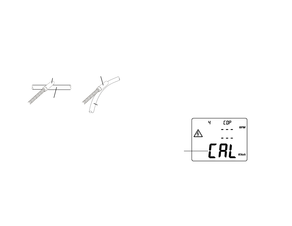
6- Place the capacitive pickup over one of the spark plug wires, and proceed to read the
measurement on the display.
Spark plug wire
Spark plug wire
Capacitive pick-up at 90°
Capacitive pick-up parallel
Fig. 6 - Capacitive pick-up on spark plug wire
Page 10
Important:
• In order to obtain consistent results when measuring Spark KVolt on spark plug wires,
the position of the capacitive pick-up relative to the spark plug wire should be the
same for every measurement.
• An easy way to obtain consistent measurements, is to position the capacitive
pick-up either at 90° or parallel to the spark plug wire (Fig 5), and then repeat the
same positioning for every spark plug wire
• Spark burn time and RPM measurements are not sensitive to the exact position of
the capacitive pick-up relative to the spark plug wire, but it has to be placed so the
instrument is capable of detecting the signal.
• When several spark plug wires are routed or bunched close together, the
capacitive pick-up may receive signals from several wires at the same time,
which could cause erroneous measurements. In these situations it may be
necessary to separate the wire under measurement from the others, in order to reduce
interference and obtain an accurate measurement.
Notes:
• Immediately after calibration, the TA500 will display a baseline value of “10.0 Spark
KVolt” by default. All the spark KVolt measurements obtained thereafter would be
relatives to the (value) module used for calibration.
• Calibration does not have any effect on spark burn time or RPM measured values
(these are absolute).
• If the TA500 is calibrated again, the Spark KVolt values obtained before and after
calibration may not be comparable.
• If not calibrated, the TA500 may show a false ‘0.0 Spark KVolt’ reading when
measuring spark KVolt on Coil on Plug and Coil near Plug systems.
Fig. 7 - Display during calibration
Burn Time
Cycles
Peak
G7
G7
mS
Flashing letters