Operation, 1 instrument description, 2 lcd display – General Technologies TA500 SmarTach+COP : Multisystem Engine Analyser User Manual
Page 3
Page 4
Page 3
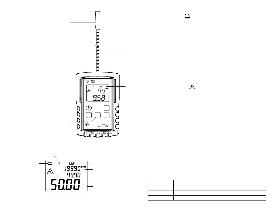
3. OPERATION
3.1 Instrument Description
1) Capacitive pick-up
2) Flexible probe
3) Protective rubber holster
4) LCD Display
5) Power ON/OFF / Reset button
6) Secondary Function / Capture button
7) Ignition System button
8) Main Function / Calibrate button
9) Engine Cycles button
3.2 LCD Display
3.2.1 LCD Display description
Fig. 1 - Instrument description
Multisystem Ignition Analyzer
Ignition
System
Function
General
Technologies
Corp.
Made in Canada
Reset
Engine
Cycles
SmarTach
+COP
Peak Voltage
Burn
time
Function
5
Secondary
Main
Calibrate
Capture
Calibrate
3
4
5
7
9
6
8
1
2
C7
Burn Time
Cycles
mS
KVolt
Spark
Fig. 2 - LCD Display
Burn Time
Cycles
mS
Spark
KVolt
Ignition System
Secondary display A
Secondary display B
Function / measurement
units
Number of cycles
Low battery indicator
Spark detected
Secondary display
function
Main display
3.2.2 Low battery indicator
The low battery symbol ‘
‘ indicates the battery voltage is below the minimum
recommended and it needs to be replaced with a new battery.
Notes:
• If the battery voltage is low, but still allows for the operation of the instrument, the low
battery indicator will turn and stay on until the battery is replaced with a new one.
• If the unit turns off immediately after being turned on, it indicates that battery
voltage is below the absolute minimum, and the battery should be replaced to prevent
malfunction.
3.2.3 Number of Cycles
Displays the number of cycles (strokes) selected: 2, 4 or DIS.
3.2.3 Ignition System
Displays the ignition system selected for the measurement: ‘
SPW’ for Spark Plug Wire,
and ‘
COP’ for Coil on Plug and Coil near Plug
3.2.4 Spark Detected
A flashing high voltage symbol ‘
‘ indicates that sparks are being detected in the ignition
system.
3.2.5 Secondary display A
Depending on the setting chosen by pressing the ‘Secondary Function / Capture’
button, it displays maximum readings, RPM or spark KVolt with measurement units
and/or function selected.
3.2.6 Secondary display B
Depending on the setting chosen by pressing the ‘Secondary Function / Capture’ button,
it displays minimum readings, RPM or spark burn time with measurement units and/or
function selected.
Note: RPM measurements in the secondary displays, are shown with the last digit
rounded to ‘0’
3.2.7 Main display
It is the main display, and it can be set to show engine RPM, spark KVolt or spark burn
time by pressing the ‘Main Function / Calibrate’ button.
3.2.8 Functions and measurement units
Displays the measurement units and/or function of the main display. The selected
function with measurement units are displayed as follows:
Display
Function
Measurement units
RPM
Tachometer
RPM (Revolutions per minute)
Burn Time mS
Spark plug burn time
mS (Milliseconds)
Spark KVolt
Spark plug peak voltage
KVolt ( 1000 x Volt)