General Technologies CT8025 Automotive Digital Multimeter User Manual
Ct8025, Safety rules, International symbols
1. SAFETY RULES
•
This meter is designed for indoor use at temperatures between 0°C to 40°C and
altitudes up to 2,000m.
• To ensure that the meter is used safely, follow all safety and operating instructions in
this operation manual. If the meter is not used as described in this operation manual,
the safety features of this meter might be impaired.
• Do not use the meter if the meter or test leads look damaged ,or if you suspect that
the meter is not operating properly.
• When using the instrument, keep your fingers behind the finger guards on the plastic
casing and probes.
• Disconnect the live test lead before disconnecting the common test lead.
• Make sure power is off before cutting, desoldering, or breaking the circuit wires. Small
amounts of current can be dangerous.
• Do not apply more than 600 VDC or 600V AC rms between a terminal and ground.
• To avoid electrical shock, use CAUTION when working above 60V DC or 25V AC
rms. Such voltages pose a shock hazard.
• Never make measurements with the battery cover off.
• To avoid electrical shock or damage to the meter, do not exceed the input limits.
2. INTERNATIONAL SYMBOLS
Important information
Dangerous Voltages
see manual
Continuity
AC
Ground
DC
Double Insulation
3. TECHNICAL SPECIFICATIONS
3.1 General Specifications
Display: 3-1/2 digits LCD, max. of 1999 display
Polarity: Automatic, (-) negative polarity indication
Zero adjustment: Automatic
Sample rate: 0.5 Sec.
Over range indication: “1” or “-1” is displayed
Power: 9-volt battery type NEDA 1604, IEC6F22
Battery life: Approx. 50 hours. (w/ alkaline batteries)
Dimension: 5.55”x2.71”x1.41” or 141x 69x36 mm.
Weight: Approx. 6.7 Oz or 190g (with battery).
Accesories: User’s Manual, Test Leads, Protective
Holster, Soft Pouch, K-type temperature
probe and 9V battery
3.2 Electrical Specifications
•
Accuracies are ±(% of reading + number of least significant
digits) at 23°C ±5°C, less than 75% RH.
4. OPERATION
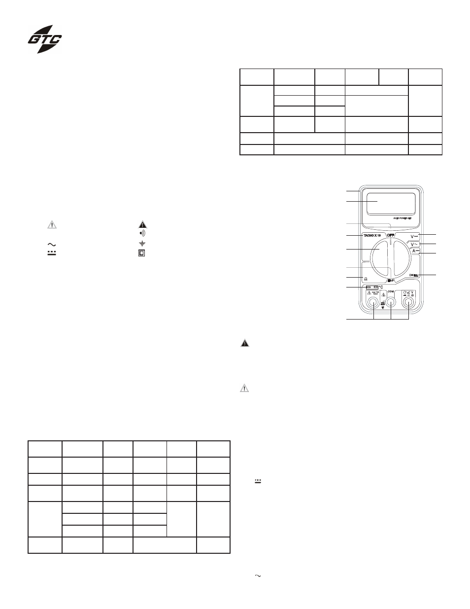
4.1 Instrument Description
1) Case
2) 3-1/2 Digit LCD display
3) Power OFF position
4) Tachometer function
5) Function/Range Switch
6) Temperature function
7) Resistance function
8) Temperature probe socket
9) Input and common connector
10) DC Voltage function
11) AC Voltage function
12) DC Current function
13) Dwell function
Function
Range
Accuracy
Input
Impedance
Remarks
Overload
Protection
DC Voltage
20V, 600V
0.8%+2
1 M
Ω
-
600 Vp-p
AC Voltage
600V
1.5%+5
450 K
Ω
40~400Hz
600 Vp-p
DC Current
10A
2.0%+5
-
10 A - 250V
Fuse
Resistance
2000
Ω, 20kΩ
0.8%+3
-
3.2V
max. test
Voltge
250 Vp-p
200kΩ, 2MΩ
1.5%+5
-
20M
Ω
3.0%+10
-
Tachometer
500 to 10000
RPM
0.8%+2
Test time: 20 Sec.
250Vp-p
4.2 Measurement Procedures
CAUTION: Maximum Input Voltage is 600Vrms,do not exceed
this rating to avoid personal injuries or damage to
the instrument. The range FUNCTION/RANGE
switch should be set to the range you want to test
before the operation.
CAUTION: Always ensure that the correct terminals are used
for the type of measurement to be made. Avoid
making connections to “live” circuits whenever
possible.When making current measurements en-
sure that the circuit is not “live” before opening it in
order to connect the test leads.
4.2.1 DC Voltage measurement
•
Connect the black test lead to the “COM” socket and red test lead
to the “V
Ω” socket.
•
Set the FUNCTION/RANGE switch to the desired range in the
“V ” function. If the voltage range is not known beforehand, set
the switch to the highest range and work down as needed.
•
Connect the test leads across the source or load under
measurement.
•
The measurement and polarity will be shown the LCD Display
when the probe are connected.
4.2.2 AC Voltage measurement
•
Connect the black test lead to the “COM” socket and red test lead
to the “V
Ω” socket.
•
Set the FUNCTION/RANGE switch to the desired range in the
“V ” function.
General Technologies Corp.
CT8025
Automotive Digital Multimeter
Function
Range
Accuracy
Input
Impedance
Remarks
Overload
Protection
Temperature
ºF Version
32 to 104ºF
3.0%+1
Built in Sensor
-
-40 to 752
ºF
0.75%+3
K-Type Thermocouple
Probe
752 to 1832
ºF
3.0%+10
Dwell Angle
3 to 8 Cyl.
0-120º
1.5%+2
0.1
º Resoultion
250 Vp-p
Continuity
Buzzer sounds when <100
Ω
Test Voltage: 2.4 V Max.
250 Vrms
Diode Test
Test Current:1.0±0.6mA
Test Voltage: 2.4 V Max.
250 Vrms
���
�
�
�
�
��� ���
�����
���
�
�
���
����
�
�
���� ����� ���
�
C
DWELL
����� � ��
TEMP
�
�
�
�
�
�
�
�
�
��
��
��
��