Appendx i: 8800 series trace moisture analyzer gro, Sensor facility ac power, Chart recorder, a/d converter etc – Teledyne 8800A/8800B - Panel / Wall mount trace moisture analyzer User Manual
Page 56: Pc, data logger etc, Alarms lo hi, Instrument circuit board pluggable block terminals
8800 Series Trace Moisture Analyzer Instruction Manual Appendices
49
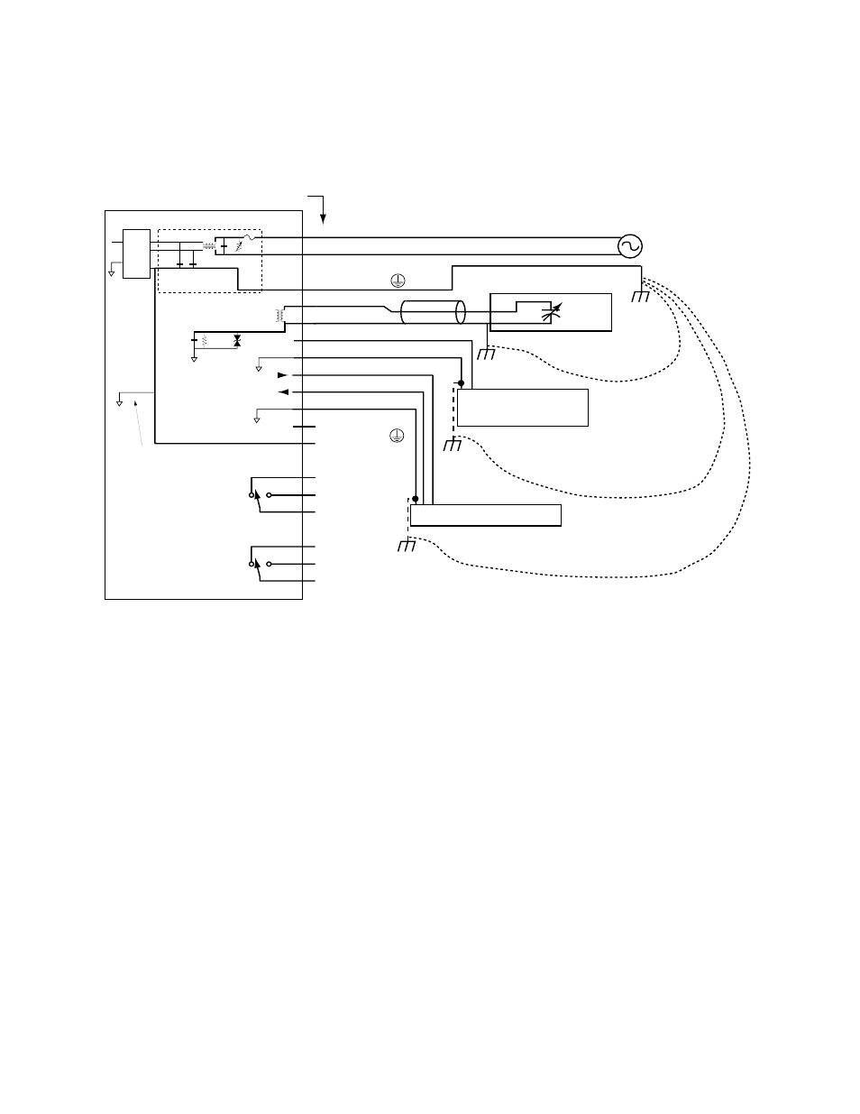
Appendx I: 8800 Series Trace Moisture Analyzer Grounding
Considerations
1. The sensor ground is isolated from the signal and frame grounds, however it is shunted to
frame ground with a 33V Transient Voltage Suppressor,1M Ohm resistor and 0.1uF capacitor
to prevent electrostatic buildup and noise pickup. When the sensor is connected to equipment
which is grounded to earth ground (because of pipes etc.), there is no ground loop because the
sensor is not connected to the earth ground on the circuit board.
2. The optional Analog Output and RS-232 Output are both referenced to the circuit board logic
ground, which is jumpered at a single point to the AC power ground. Therefore if these out-
puts are connected to equipment which connects the signal grounds to earth ground (this is a
common occurrence in PC's), then a ground loop may be formed. This can be best avoided by
removing the signal to earth ground connection at the termination equipment; if that is not
possible then the AC power ground connection to 8800 Series Trace Moisture Analyzer logic
ground may be removed but this may cause a EMI problem. Please consult with your repre-
sentative for information on optional isolated analog and RS-232 outputs. Keep in mind that
in general, a ground loop on a digital line such as RS-232 will not cause problems.
3. The Earth Safety Ground (AC GROUND) at pin 4, should not be omitted since the RFI filter
capacitors will cause half the line voltage to develop at the instrument’s ground. This may
have safety and EMI implications.
4. When installing DC powered instruments (15 to 30VDC at pins #12 and #11), similar condi-
tions may exist, if the DC power source is earth grounded.
7
A-OUT
8
A-RET
Chart recorder,
A/D converter etc.
Sensor
Facility
AC Power
PC, Data Logger etc.
21 C
20 NO
18 Not Connected
14 Not Connected
3
Not Connected
19 NC
17 C
16 NO
15 NC
ALARMS
LO
HI
11 RET
10 RxD
9
TxD
2
AC NEUTRAL
1
AC LIVE
4
AC GROUND
13 AC GROUND
Analog Output 4/20mA
5
SIG-IN
6
SIG-RET
12 PS+
white
black
0.5A 250V
0.1uf
0.1uf
0.0047uf
0.0047uf
4.3mH
RFI filter board
275VAC
Power Supply
Module
Sensor
Measuring
Circuitry
1M Ohm
33V 400W
Logic ground and AC
Power ground are
connected for safety
and electromagnetic
interference
considerations
Instrument Circuit board
Pluggable Block Terminals
RS 232 I/O
Earth
Safety
Ground
Sensor casing connects to piping
Possible Earth Ground at Analog Output monitoring equipment
Possible Earth Ground at terminating equipment
conn
ecti
on
throu
gh struc
tural members pipes
etc
. d
oe
s
N
O
T
c
a
u
se
g
ro
u
n
d
lo
op
conne
ction thro
ugh eq
u
ipment ground CO
ULD
c a
us
e
a
g
ro
u
n
d
lo
o
p
connection throug
h
equ
i
pment ground
COULD
ca
us
e a
gr
ou
nd
lo
op