Teledyne 7320 - NDIR analyzer User Manual
Page 22
2 Installation
Model 7320
2-8
Teledyne Analytical Instruments
2.3.3.3
Digital Remote Cal Inputs
Accept 0 V (off) or 24 V dc (on) inputs for remote control of calibra-
tion. (See Remote Calibration Protocol below.) See Figure 2-5 for pin
connections.
Zero:
Floating input. A 5 to 24 V pulse input across the + and –
pins puts the analyzer into the
Zero
mode. Either side may be
grounded at the source of the signal. A synchronous signal
must open and close the gas control valves appropriately.
Span:
Floating input. A 5 to 24 V pulse input across the + and –
pins puts the analyzer into the
Span
mode. Either side may
be grounded at the source of the signal. A synchronous signal
must open and close the gas control valves appropriately.
Cal Contact: This relay contact is closed while analyzer is spanning
and/or zeroing. (See Remote Calibration Protocol below.)
Table 2-5: Remote Calibration Connections
Remote Calibration Protocol: To properly time the Digital Remote
Cal Inputs to the Model 7320 Analyzer, the customer's controller must
monitor the Cal Relay Contact.
When the contact is OPEN, the analyzer is analyzing, the Remote Cal
Inputs are being polled, and a zero or span command can be sent.
When the contact is CLOSED, the analyzer is already calibrating. It
will ignore your request to calibrate, and it will not remember that request.
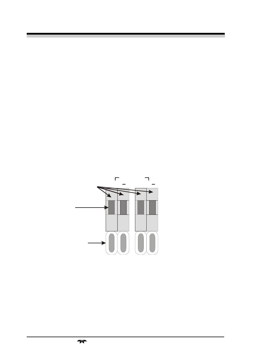
R E M O TE
SPAN (2 4V )
R E M O TE
ZE R O (24V )
+
+
P re s s h e re to
in se rt w ire .
R e le a se to h o ld .
In s e rt w ire
h e re .
DIGITAL INP UTS
F lo a tin g