Teledyne 7320 - NDIR analyzer User Manual
Page 19
Infrared Gas Analyzer
Installation 2
2-5
Teledyne Analytical Instruments
2.3.3.1
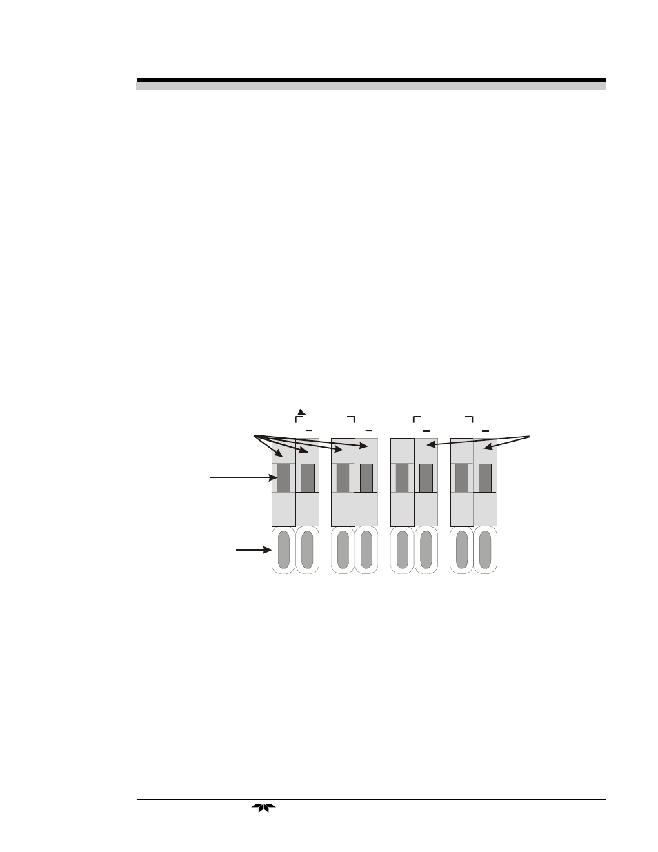
Analog Outputs
There are four DC output signal pins—two pins per output. For polar-
ity, see Figure 2-3. The outputs are:
0–1 V dc % of Range: Voltage rises linearly with increasing concentration,
from 0 V at 0 concentration to 1 V at full scale.
(Full scale = 100% of programmable range.)
0–1 V dc Range ID:
0.25 V = Range 1, 0.5 V = Range 2, 0.75 V =
Range 3, 1 V = Cal Range.
4–20 mA dc % Range: Current rises linearly with concentration, from 4
mA at 0 concentration to 20 mA at full scale. (Full
scale = 100% of programmable range.)
4–20 mA dc Range ID: 8 mA = Range 1, 12 mA = Range 2, 16 mA =
Range 3, 20 mA = Range 4.
Figure 2-3: Analog Output Connections
Examples:
The analog output signal has a voltage which depends on gas concen-
tration relative to the full scale of the range. To relate the signal output to the
actual concentration, it is necessary to know what range the instrument is
currently on, especially when the analyzer is in the autoranging mode.
The signal output for concentration is linear over the currently selected
analysis range. For example, if the analyzer is set on a range that was defined
0-1 V O /P
% R A N G E
V O LTA G E
0-1 V O /P
R A N G E ID
4-20m A O /P
% R A N G E
4-20m A O /P
R A N G E ID
+
+
+
+
P re s s h e re to
in se rt w ire .
R e le a se to h o ld .
In se rt w ire
h e re .
C U R R E N T
N e g a tiv e
g ro u n d
F lo a tin g
C u rre n t
O p tio n a l