Teledyne 3000MB - Paramagnetic oxygen analyzer User Manual
Page 33
Percent Oxygen Analyzer
Installation 3
3-13
Teledyne Analytical Instruments
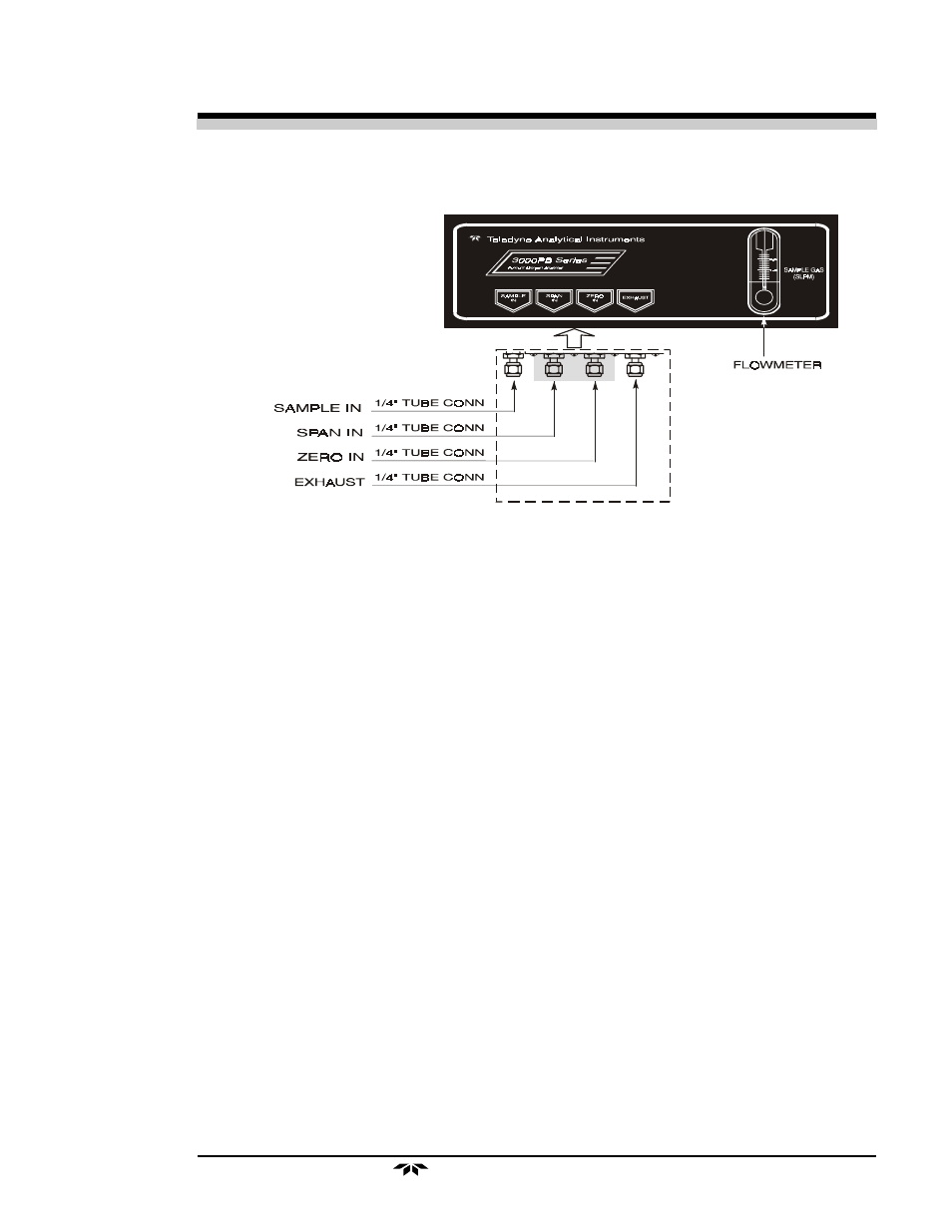
Figure 3-10: Gas Connector Panel
SAMPLE IN: In the standard model, gas connections are made at the
SAMPLE IN
and
EXHAUST OUT
connections. Calibration gases must be
Tee'd into the Sample inlet with appropriate valves.
The gas pressure in should be reasonably regulated. Pressures between
3 and 40 psig are acceptable as long as the pressure, once established, will
keep the front panel flowmeter reading in an acceptable range (0.1 to 2.4
SLPM). Exact figures will depend on your process.
If greater flow is required for improved response time, install a bypass
in the sampling system upstream of the analyzer input.
Note: If you have the –V option, The above numbers apply instead to
the vacuum at the EXHAUST OUT connector, described be-
low, with minus signs before the pressure readings.
ZERO IN and SPAN IN: These are additional ports, included on
models with the -C option, for inputting span gas and zero gas. There are
electrically operated valves inside for automatic switching between sample
and calibration gases. These valves are completely under control of the
3000PB Electronics. They can be externally controlled only indirectly
through the Remote Cal Inputs, described below.
Behind Panel