4 sample system – Teledyne 3000MA - Paramagnetic oxygen analyzer User Manual
Page 17
2-5
Percent Oxygen Analyzer
Operational Theory 2
Teledyne Analytical Instruments
(0% 0
2
) - (Cross Interference Value) = Zero Point Value
0% -(-0.137) = +0.137%0
2
2.4
Sample System
The sample system delivers gases to the sensor from the analyzer gas
panel inlets. Depending on the mode of operation either sample or calibration
gas is delivered.
The Model 3000MA sample system is designed and fabricated to ensure
that the oxygen concentration of the gas is not altered as it travels through the
sample system. The sample encounters almost no dead space. This minimizes
residual gas pockets that can interfere with low percent range analysis.
The sample system for the standard instrument incorporates ¼ inch tube
fittings for sample inlet and outlet connections at the rear panel. For metric
system installations, 6 mm adapters are available with each instrument to be
used if needed. The sample or calibration gas flowing through the system is
monitored by a flowmeter downstream from the sensor.
The gases delivered to the instrument should be at constant pressures and
flow rates and must exit freely into the ambient atmosphere. The Span, Zero
and Sample gases should be delivered at constant pressures of about 10 psig
(Range 5-20). The flow rate must be maintained at about 700 cc/minute (Range
500-900) and must exit freely into atmospheric pressure.
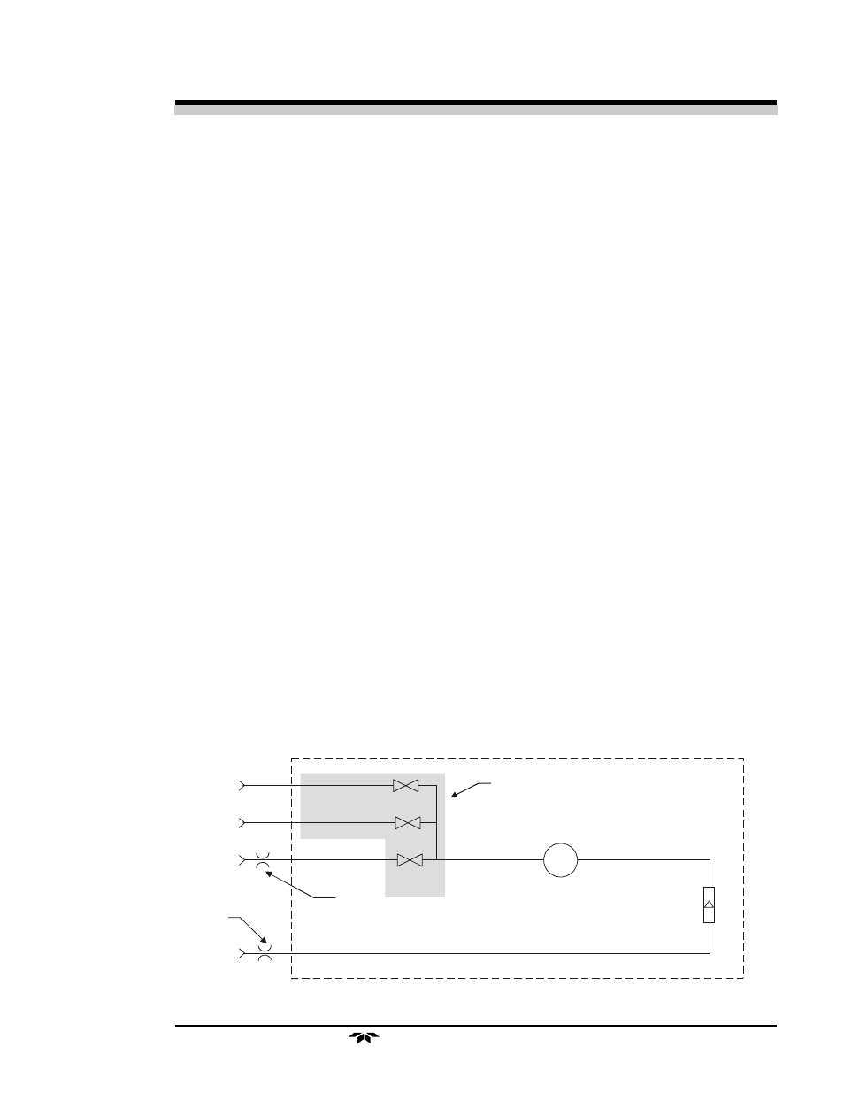
Figure 2-4 is the flow diagram for the sampling system. In the standard
instrument, calibration gases (zero and span) can be connected directly to the
Sample In port by teeing to the port with appropriate valves. The shaded por-
tions of the diagram show the components added when the –C options are
ordered. The solenoid valves, when supplied, are installed inside the 3000MA
enclosure and are regulated by the instruments internal electronics.
Figure 2-4: Flow Diagram
In vacuum service the
restrictor should be
placed here.
Sample In
Span In
Zero In
Flowmeter
Exhaust Out
Solenoid
Valves
Restrictor
Cell
In normal service the
restrictor should be
placed here.
Components in the shaded area are in
the -C option (internal control valves)
only and are not shown in the piping
diagram above.