Teledyne 1220 - Multipoint flammable gas and vapor detection system User Manual
Page 26
3 Installation
Model 1220
3-8
Teledyne Analytical Instruments
module may be accomplished by sliding the module into the chassis until the
top and bottom screws can be engaged, engaging them, tightening the
bottom (jack) screw to reconnect the module, and then tightening the top
(retaining) screw.
WARNING: Disconnect power before performing any of the
following. These operations should only be per-
formed by a qualified service technician.
3.4.1 Removing the Channel Module Cover
In order to perform the actions in the following sections 3.4.2, 3.4.3 and
3.4.4, the cover of the channel module must be removed. To remove the
cover, unscrew the two 6-32 screws that hold the cover in place, then slide
out the cover.
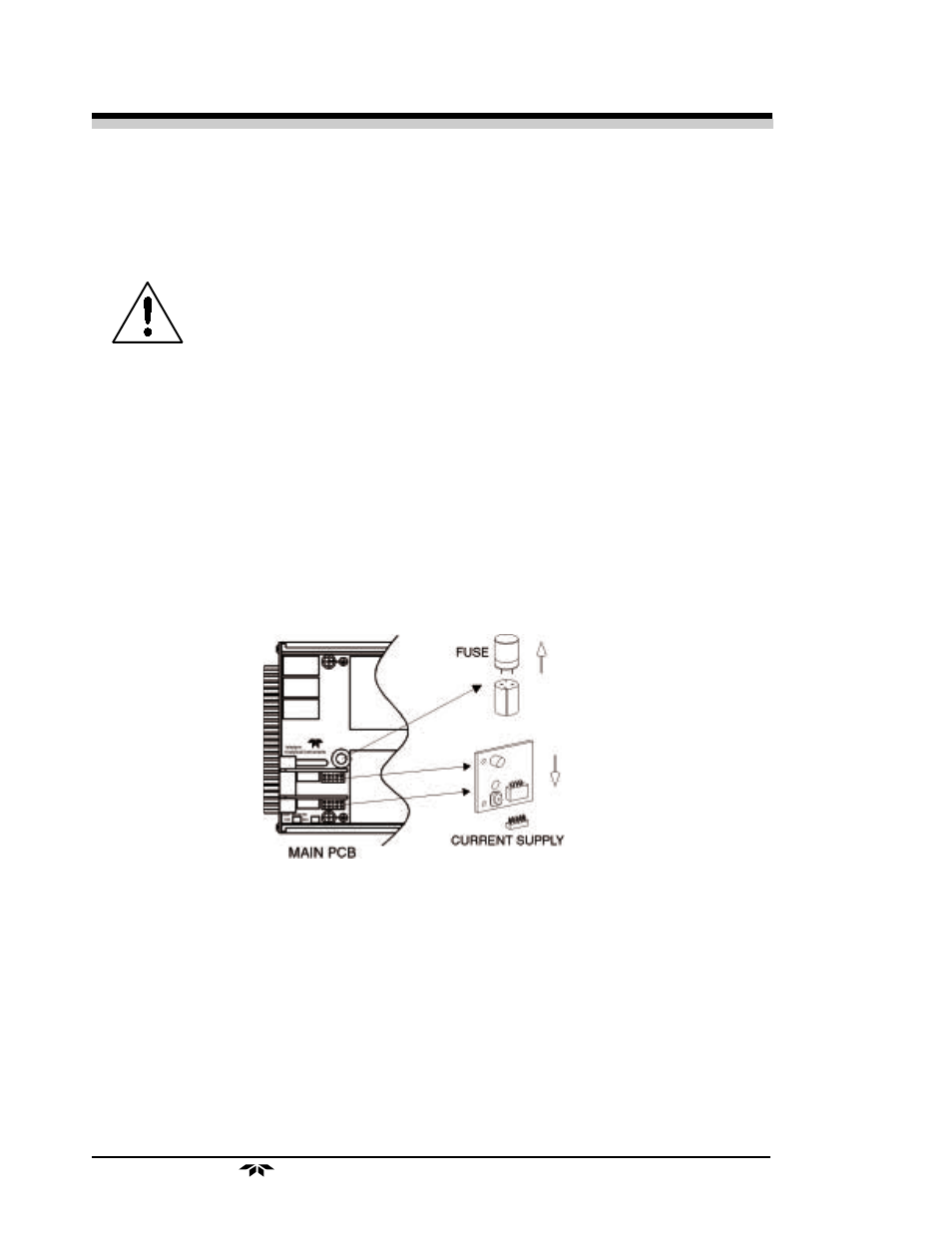
3.4.2 Changing the Fuse
Remove the channel module cover as in section 3.4.1. The fuse is
located as shown in the Figure 3-4
3.4.3 Adding or Removing the Second Sensor PCB
The model 1220 channel module may be configured for operation with
either one or two combustible sensors. Each sensor's power supply resides
on a sensor PCB. The location of the two sensor PCBs is shown in Figure
3-4. The single sensor PCB is factory installed at location SENSOR 1. In
order to use two sensors with a single channel module, an additional sensor
PCB must be installed at location SENSOR 2.
To add or remove the SENSOR 2 PCB, first remove the channel
module cover as in section 3.4.1 and add/remove the second sensor PCB as
shown in Figure 3-4.
Figure 3-4 Fuse and Sensor PCB Locations