Control unit - block diagram – Teledyne 1220 - Multipoint flammable gas and vapor detection system User Manual
Page 12
2-2
2 Operational Theory
Model 1220
Teledyne Analytical Instruments
for operation in the “non fail-safe” mode by setting the configuration
jumpers as indicated in the installation section 3.3.2. Each of these relays
provides SPDT contacts for operation of external devices.
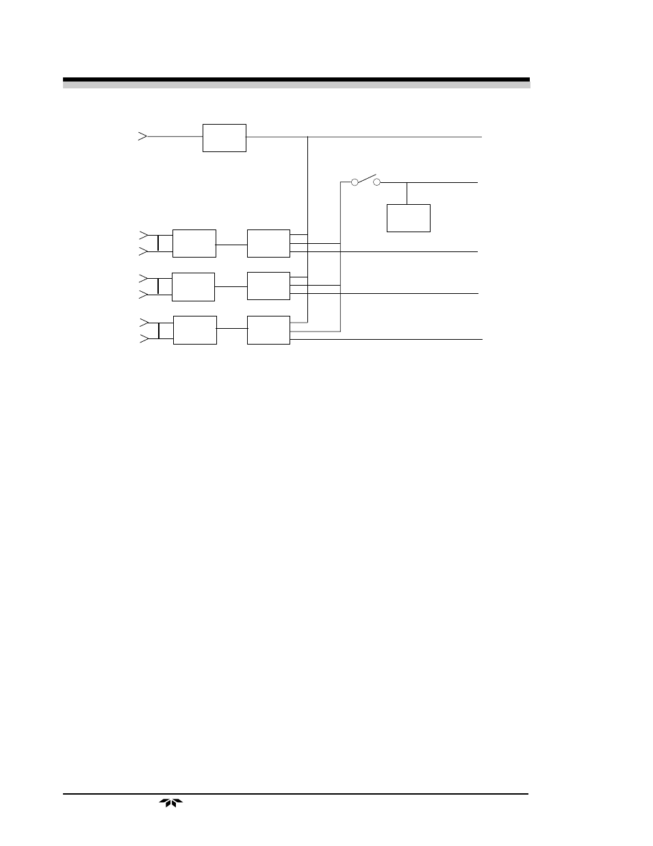
An audible alarm is actuated when any alarm state occurs. This
audible alarm may be disconnected by switching the AUDIBLE ALARM
control switch to the BYPASSED position. When this is done, the red
lamp on the system module is illuminated as an indication that the audible
alarm is not functioning.
The Control Unit is the power entry and distribution point. The 1220
system contains universal power supplies that operate on 100-240 VAC,
50/60Hz. The power switch on the Control Unit switches power for the
entire system. The line is protected by two 3 Amp fuses, accessible from
the front panel.
A 1/8 A fuse is furnished for the electronic circuitry of the Control
Unit. The green power LED indicates that the Unit is ON.
Alarm switch S2 has two positions. Normally, the switch is set to the
ACTIVE position which provides for audible alarm when any of the
Channel Modules goes into the alarm state. When set to the BYPASS
position, the local audible alarm is turned off.
SIGNALS FROM
CHANNEL MODULES
POWER
SWITCH
INTERNAL
BUZZER
PRIMARY
POWER
DRIVERS
RELAYS
AUDIBLE
ALARM BYPASS
*HIGH
*CAUTION
FAILURE
POWER TO
CHANNEL
MODULES
POWER FOR
EXTERNAL
AUDIBLE
ALARMS
CAUTION
FAILURE
RELAY
CONTACT
ACTUATION
HIGH
Control Unit - Block Diagram