Installation, Drain/fill connection, Catch tank – Fulton Hopkins (HPN) Horizontal Coil Thermal Fluid (hot oil) Heater User Manual
Page 26
© The Fulton Companies 2014
INSTALLATION
HPN-IOM-2014-0416
SECTION 2
2-20
2. Under normal operating conditions, the catch tank
should be empty. Fluid that is expelled into the tank
should not be reintroduced into the system.
3. Ensure the vent from the catch tank is located and
installed in such a manner as to protect personnel and
property from discharge of steam, water, and thermal
fl uid. Vent outlet should be positioned in a safe location
outside the heater room.
Drain/Fill Connection
The system is usually fi lled from the lowest point, with the aid
of a pump. On skid-mounted units, a drain and fi ll connection
is provided in the inlet piping to the pump. See Figure 11.
11. An inspection opening is located at the highest point
on the tank. Access to this port is recommended but
not required.
12. Refer to the maintenance schedule for
recommendations on draining the buff er tank. For
positioning of all connections on tank, see Figure 9.
Catch Tank
Adhere to the following for the catch tank:
1. Ensure the heater safety relief valve outlet and
connections on the DA tank are piped to a safe catch
tank. The catch tank must be appropriately sized based
on the system volume and confi guration.
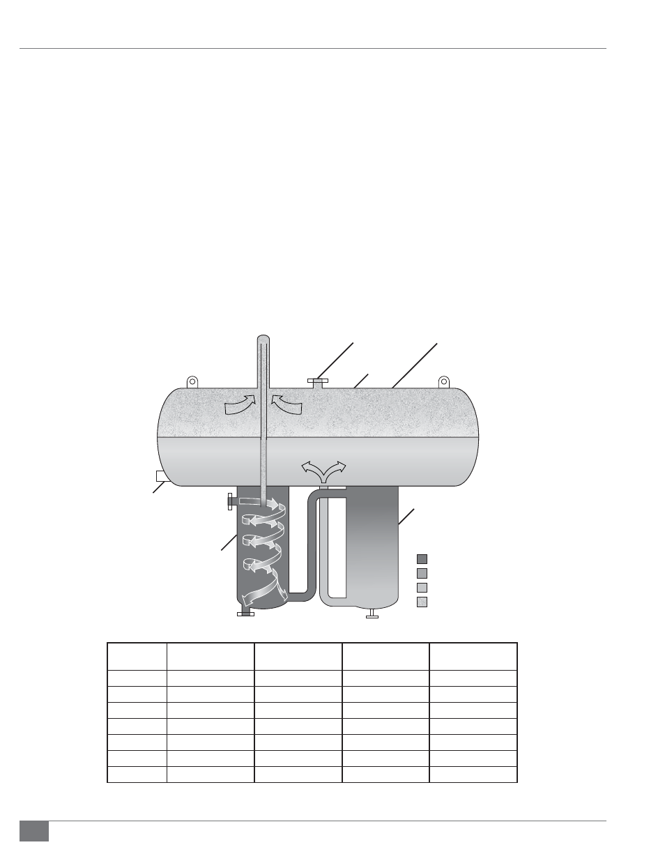
Vent for Piping
to Safe Catchment
Expansion
Tank
Liquid
Level
Switch
Fluid Out
Fluid In
Deaerator
Section
Thermal
Buffer
Section
Hot Fluid
Medium Fluid
Cool Fluid
Gases (Steam)
Expansion
Volume
Drain
Model
Capacity (gallons)
Initial Fill (gallons)
Available for
Expansion (gallons)
Max System
Volume
FT-200-L
52
25
46
184
FT-500-L
132
40
121
525
FT-1000-L
264
80
232
1000
FT-1500-L
397
90
380
1400
FT-2000-L
528
145
444
1700
FT-3000-L
793
215
717
2600
FT-5000-L
1310
300
1168
4600
FIGURE 8 - EXPANSION TANK DETAILS