Installation – Fulton Electric (FB-L) Steam Boiler User Manual
Page 14
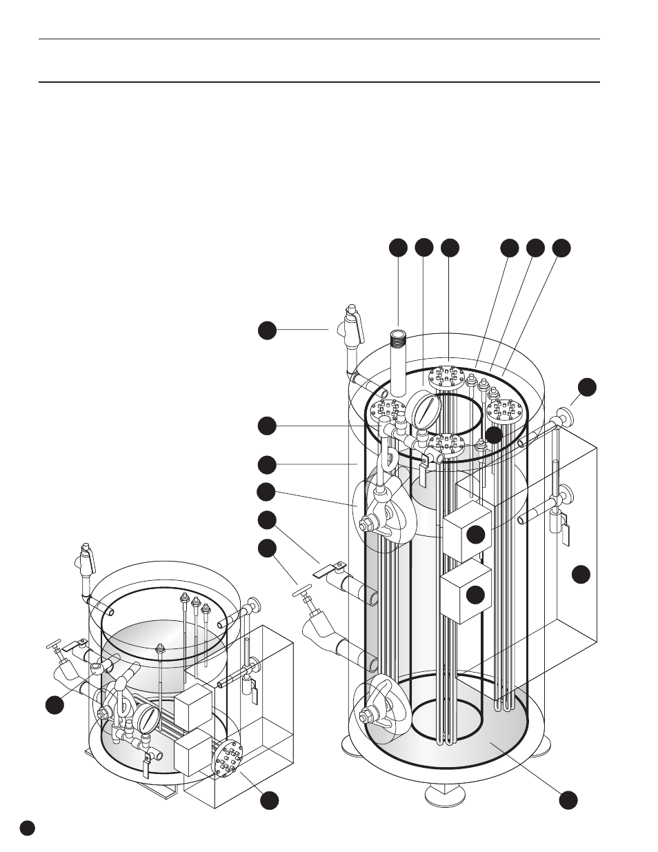
1. Pressure Vessel Is Built to ASME Code
5 Year Warranty
2. Electrical Control Panel Box
3. Electric Heating Elements
4. Low Water Cut Off Probe
5. Second (auxiliary) Low Water Cut Off
Probe
6. Pump “On” Probe
7. Pump “Off” Probe
8. Sight Glass Assembly
9. Operating pressure control
10. High Limit Pressure Control w/ manual
reset
11. Steam Outlet
12. Safety Valve
13. Steam Guage Assembly
14. Steam Pressure Guage
15. High Temperature Insulation Surrounds
The Pressure Vessel
16. Large (3” x 4”) Easy Access Handholes
17. Feedwater Shut Off Valve
18. Blowdown Valve
19. Water Bottle Assembly for 300 to 1000
kW Only
NOTE:
All Fulton Electric Steam Boilers have a
second (auxiliary) low water cut-off
probe
Electric IOM
Installation
10
Component Locations of the Fulton 12 to 1000 kW
(1.2 to 100BHP) Steam Boilers
3
11
1
3
4
6
7
8
11
12
13
14
16
17
18
15
2
9
10
5
12 to 36 kW (1.2 to 3.6 BHP)
Element(s) are horizontally mounted at the
bottom of the pressure vessel. All probes
are located in the top of the boiler.
50 to 200 kW (5 to 20 BHP)
Elements are vertically mounted. All probes
are located in the top of the boiler.