Iii. installation, Map of the motherboard, Map of board) iii. inst alla tion – Asus P/E-P55T2P4D User Manual
Page 10
4
P/E-P55T2P4D User’s Manual
III. INSTALLATION
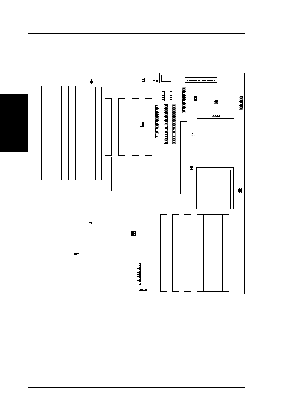
Map of the Motherboard
ISA
Slot 1
PCI Slot 4 / MediaBus 2.0
PCI Slot 2
PCI Slot 1
PCI Slot 3
EISA
Slot 1
Floppy Drives
Parallel Printer
Keyboard
PS/2
Mouse
COM 1
COM 2
Infrared Con.
Case Connectors (CON 3)
IDE LED
JP24
JP25
EISA
Slot 2
EISA
Slot 3
EISA
Slot 4
JP27
JP26
JP39
JP15
JP16
JP17
JP18
F
AN2
F
AN1
Processor 1
CPU ZIF Socket 7
Processor 2
CPU ZIF Socket 7
JP29
JP30
JP32
Pipelined Burst Level 2 Cache Slot
SIMM Slot 1 (Bank 0)
SIMM Slot 2 (Bank 0)
SIMM Slot 3 (Bank 1)
SIMM Slot 4 (Bank 1)
SIMM Slot 5 (Bank 2)
SIMM Slot 6 (Bank 2)
SIMM Slot 7 (Bank 3)
SIMM Slot 8 (Bank 3)
Primary IDE
Secondary IDE
JP37
JP38
JP34
JP3
JP2
JP1
1
JP12
JP9
JP10
COM2/Infrared
ECP DMA CH1/3
256/512 L2 Cache
JP5
JP6
JP7
JP8
JP19
JP20
JP21
CPU Freq
Ratio
APIC
P54C/P55C Processor
12V Fan Pwr
Boot Block Programming
CPU External Freq
CMOS RAM Operation/Clear
Vio Voltage
Vcore Voltage
Processor Type
PCI 1 Master/Slave
(SMC37C665IR Only)
(SMC37C665IR/37C669 Only)
Board Power Input
P8
P9
(Map of Board)
III. INST
ALLA
TION