Perrycraft SportQuest Upgrade - TM or ST Style Track User Manual
Page 2
Measure Here
Stanchion (outside,
toward edge of
vehicle roof)
Adjustment Knob
Stanchion (inside,
toward center of
vehicle roof)
Open side of bkt.
Stanchion Pin
Stanchion
Foot Bkt.
Side Rail (track) Assembly
Stanchion/Track
Clamp Bracket
Mark Here
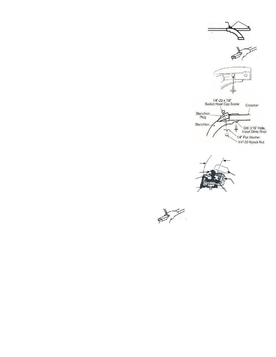
Drill 3/16" Hole,
Install Drive Rivet
Stanchion Cavity
Fig. 3
Fig. 5
Fig. 4
Mark Here
Fig. 1
Fig. 2
Fig. 3
INSQ-UPGD.TM 2 of 2 120918
7. Measure and note distance from end of cavity to end of crossbar (see Fig. 3)
and divide by 2, making note of the resulting dimension.
8. Remove stanchion/crossbar assemblies from side rails by removing knobs and sliding
foot brackets out of clamp brackets.
9. Remove stanchion plugs from the two "plugged" stanchions.
10. Slide crossbars thru stanchions until same length of bar (using "resulting dimension" from
Step 7) is extending beyond each support. Visibly mark top of both crossbars at end of opening
in stanchions (see Fig 4).
11. Insuring that all stanchions remain aligned with their respective marks on bars (per Step 10),
drill 3/16 holes through bottom side of crossbars in stanchion hole as shown in Fig. 5.
Insert the 3/16 drive rivets into drilled holes, and tap rivet mandrel pin firmly with
hammer until flush with rivet head. Repeat for each stanchion.
12. Install crossbar end caps. Reinstall stanchion/crossbar assemblies into side rails using
procedure in Steps 3-5. To adjust position of crossbars, loosen adjustment knob,
slide crossbars to desired position, and re-tighten knobs.
OPTION 2 - Stanchion-Fit Crossbars:
1. Install stanchion plugs into two stanchions using 1/4"-20 x 7/8" cap screws, 1/4"
flat washers and nylock nuts as shown in Fig. 1.
2. Slide one "plugged" stanchion on to end of each crossbar, butting end of bar firmly
against stanchion plug. While insuring bar remains butted against plug, drill 3/16"
hole in bottom of crossbar thru remaining hole on underside of stanchion neck.
Install Drive Rivet in drilled hole as shown in Fig. 1, tapping rivet mandrel pin
firmly with hammer until flush with rivet head.
3. Push one "open" stanchion onto other end of each crossbar, positioning each stanchion
relative to width of existing tracks.
4. Insert stanchion/track clamp brackets into tracks as shown in Fig. 2.
5. Slide stanchion foot brackets into the stanchion/track clamp brackets,
aligning bracket ends.
6. Install adjustment knobs into threaded holes in stanchion/track clamp
brackets.
7. Adjust crossbar position by rotating adjustment knobs 1-2 turns
counter-clockwise, and slide one crossbar assembly to front, the
other to rear. Rotate knobs clockwise firmly to securely lock
stanchions in place.
8. With stanchion/crossbar secured to tracks, mark end of
crossbars on end extending through stanchion at end
of cavity as shown in Fig. 3.
9. Remove stanchion/crossbar assemblies from side rails by removing adjustment knobs and sliding foot brackets out of clamp
brackets.
10. Remove "open" stanchions from crossbars, and square cut the crossbars where marked in Step 8. Install stanchion plugs
into two "open" stanchions using 1/4"-20 x 7/8" cap screws, 1/4"flat washers and nylock nuts as shown in Fig. 1 above.
11 . Slide one stanchion on to end of each crossbar, butting end of bar firmly against stanchion plug. While insuring bar remains
butted against plug, drill 3/16" hole in bottom of crossbar thru remaining hole on underside of stanchion neck. Install
Drive Rivet in drilled hole as shown in Fig. 1, tapping rivet mandrel pin firmly with hammer until flush with rivet head.
12. Reinstall stanchion/crossbar assemblies into side rails by sliding stanchion foot brackets into stanchion/track clamp
brackets and reinstalling adjustment knobs as shown in Fig. 2 above.
13. Slide crossbars to desired location and rotate knob clockwise until tight.