Perrycraft Aventura Roof Racks User Manual
Roof rack installation instructions
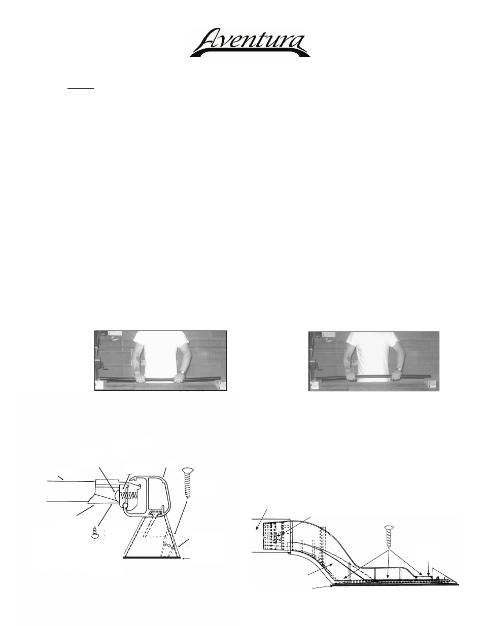
Increase Rail Curvature-Rail Upside Down
Decrease Rail Curvature-Rail Right Side Up
Diagram 2
3) Slide crossbar connectors into opening on inside
of rails as shown in Diagram 1, positioning relatively
equidistant from each end of rails. Loosely tighten
connector lock tab screws using 5/16" allen wrench
provided.
4) Install end supports to side rails using the #8 x 5/8"
self-threading screws as shown in Diagram 2 below.
Do not tighten screws completely at this point.
Crossbar
Crossbar
Connector
1/4-20 x 7/8"
Socket Head
Machine Screw Connector
Lock Tab
Side
Rail
#10 x 1"
Oval-head
Waxed
Screw
Center Post
(when applicable)
Neoprene
Pad
#8 x 5/8"
Screw
#10x3/4
Waxed Screws
#8 x 5/8 Screw
Nylon
Washer
Support Base
(A-R or A-L)
Side Rail
Neoprene Pad
Diagram 1
1/4 S. Steel
Flat Washer
Note: Aventura
racks are designed
with a slot in the underside
of the connectors to enable
rack width to be adjusted to
accommodate a broader range of roof sizes as well as those
roofs having non-parallel body seams and/or rib patterns. The
head of the #8 screw acts as an adjustment stop (re: Step 5
on Page 2 of this instruction sheet).
I N AV- R R K ( P a g e 1 o f 2 ) 1 3 0 8 0 7
Roof Rack Installation Instructions
CAUTION: Do not use the mounting hardware contained in this roof rack kit for installation on Fiberglass or
Composite Plastic surfaces. Supplemental hardware pack, part# HWAVTC-UV, is required for installation on such
non-metal surfaces. Please contact the Distributor from whom the rack was purchased or contact the Perrycraft
Customer Service Dept at 800-777-7081 to obtain the necessary supplemental hardware pack if installing this
roof rack on a Fiberglass or Composite Plastic surface.
CONTENTS: 2 - side rails, 2 - Left end supports and mating covers; 2 - Right end supports and mating covers;
2 - Crossbars; 4 - Crossbar Connector Assemblies; 5 - PVC Roof Slats; 1 hardware pack
containing 8-#8x5/8 self-threading truss-head screws, 12-#10x3/4 waxed-tip pan head screws,
4-1/4 Stainless Steel Flat Washers, 2-Side Rail Center Posts (68" & 78" Rails) or 4-Center Posts
(88" Rails); 2-#10x1 waxed-tip oval-head screws (68 & 78" Rails) or 4-screws (88" Rails); 1-5/16"
Allen wrench; 1-instruction sheet.
Tools required: Phillips screwdriver; electric drill; 1/8 drill bit; center punch; pencil or marker.
1) As a universal roof rack designed to fit several different vehicles, the bow / curvature of the side rails may
or may not exactly match the roof contour of a particular vehicle. NOTE: The rails should be dry fit to
the roof panel before assembling the roof rack. Carefully place one of the rails (without end supports
or center support posts) on the vehicle roof in the approximate location to be installed. The curvature of the
rail should approximate the roof contour. If rail is under-curved and there is more than a 3/16 space between
the ends of the rail and the vehicle roof panel, or over-curved and there is more than a 3/16 space between
the center of the rail and the roof panel, bench adjusting the curvature of the rails is required. Adjust by
suspending the rail between two points (4x4 wooden blocks, two tables, etc). To increase the curvature, start
with the rail upside down; to decrease the curvature, start with the rail right side up (see appropriate illustration
below). With hands spaced shoulder-width apart, apply sufficient pressure to the rail to increase or decrease
the curvature as desired. Repeat this process for both rails.
Important Note: While made of extruded aluminum, the rails are heat-treated for added strength.
Therefore, several applications of adequate springing pressure may be required to modify the curvature
of the rails.
2) Slide center posts into groove on bottom of rails
(applicable only on side rails of 68 or longer) as
shown in Diagram 1 below.
(over)