Perrycraft Aventura Roof Racks User Manual
Page 2
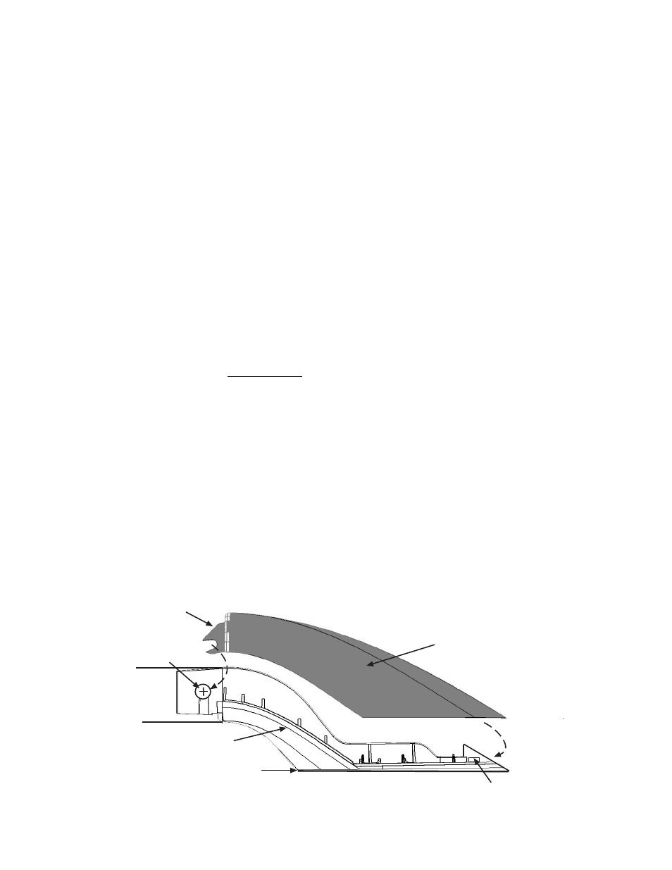
Slide vertical blade of cover into gap between base and wall of side
rail, insuring slot in blade seats around shank of screw. Rotate
opposite end of cover downward until it contacts the support base,
then apply moderate pressure at the end until cover snaps into tab
slots at end of base.
Support Cover
(mate A-L or A-R)
Support Base
(A-L or A-R)
Side
Rail
#8x5/8"
Screw
Neoprene Pad
IMPORTANT NOTE: This Roof Rack Kit contains 4 Rail Supports with mating Right and Left Bases
and Covers. These components are identified by "A-L" or "A-R" molded on the top surface of each
Base and inside surface of each Cover. When installing Covers, insure that Covers are mated with
appropriate Bases.
Mating Tab Slot
Vertical
Blade
I N AV- R R K ( Pa g e 2 o f 2 ) 1 3 0 8 0 7
5) Install crossbars into crossbar connectors and secure with #8 x 5/8" screws thru slot-opening in connector
and into pre-drilled holes in bottom of crossbars as shown in Diagram 1 on Page 1 of this instruction sheet.
Note: The slip-joint style connectors provide limited, non-parallel installation of side rails on vehicles having
rib patterns or roof panel seams that are not parallel to each other. Typically rails should be installed parallel
to each other.
6) Place assembled rack in desired position on vehicle roof. If center posts are included in the unit, the post
should be positioned approximately midway along the length of the rails. Mark locations of all mounting
holes.
7) Place roof slats evenly spaced left to right and running parallel to side rails. If the vehicle roof has raised
ribs formed in the roof panel, the roof slats should be positioned on top of said ribs provided the rib surface
is wide enough. On vehicles with more than 5 ribs in the roof, the roof slats should be installed on the 4
interior center ribs. Mark location of all slats being used.
8) Remove the rack and roof slats from vehicle roof. Clean the roof where the slats will be located, using an
adhesion cleaner/promoter such as Pro-Bond, Tite-R-Bond, etc. If such a promoter is not available, denatured
alcohol or acetone should be used to clean the roof panel.
9) Peel back several inches of the red liner on the slat tape and reposition the slat in the marked location,
pressing firmly at the point of adhesion to the roof panel. Continue peeling tape liner from underneath the
slat and press firmly to adhere the slat to roof. Repeat for each slat being installed. NOTE: Do Not wash
vehicle for 48 hours to insure proper adhesive curing.
10) Lightly center punch each marked mounting hole location. Drill fastener pilot holes using 1/8 drill bit taking
care not to allow drill bit to penetrate vehicle headliner. Clear all metal drill chips from roof panel and apply
a coat of primer or rust inhibitor to the bare metal edges of each hole.
11) Reposition rack on roof panel and install using the #10 x 3/4 waxed screws as shown in Diagram 2 on
Page 1 of this instruction sheet. IMPORTANT: At outermost hole in each end support, place a 1/4 Stainless
Steel flat washer (included) under head of each screw. Note: Use #10 x 1 Oval Head waxed screws to
secure center posts (if included) as shown in Diagram 1 on Page 1.
12) Loosen the #8 x 5/8" support-to-rail screws approximately 2-3 complete turns to allow installation of the
support covers.
13) Position a mating support cover (A-L cover to A-L support; A-R cover to A-R support) as shown in diagram
below with the vertical blade of the cover sliding into the gap between the side wall of the end support
tongue and the center wall of the rail extrusion. With blade correctly inserted/aligned at the end of rail, rotate
the cover downward until it contacts the support base, and apply moderate downward pressure at the tapered
end of the cover until the lock tabs at the end of the cover snap into the mating tab slots at the end of the
support base.
14) With covers properly installed, securely tighten the four #8 x 5/8" support-to-rail screws while applying slight
pressure to the top of each cover to insure proper seating of the cover to the mating support base.