7\sh ri *dv – American Dryer Corp. AD-75 User Manual
Page 32
28
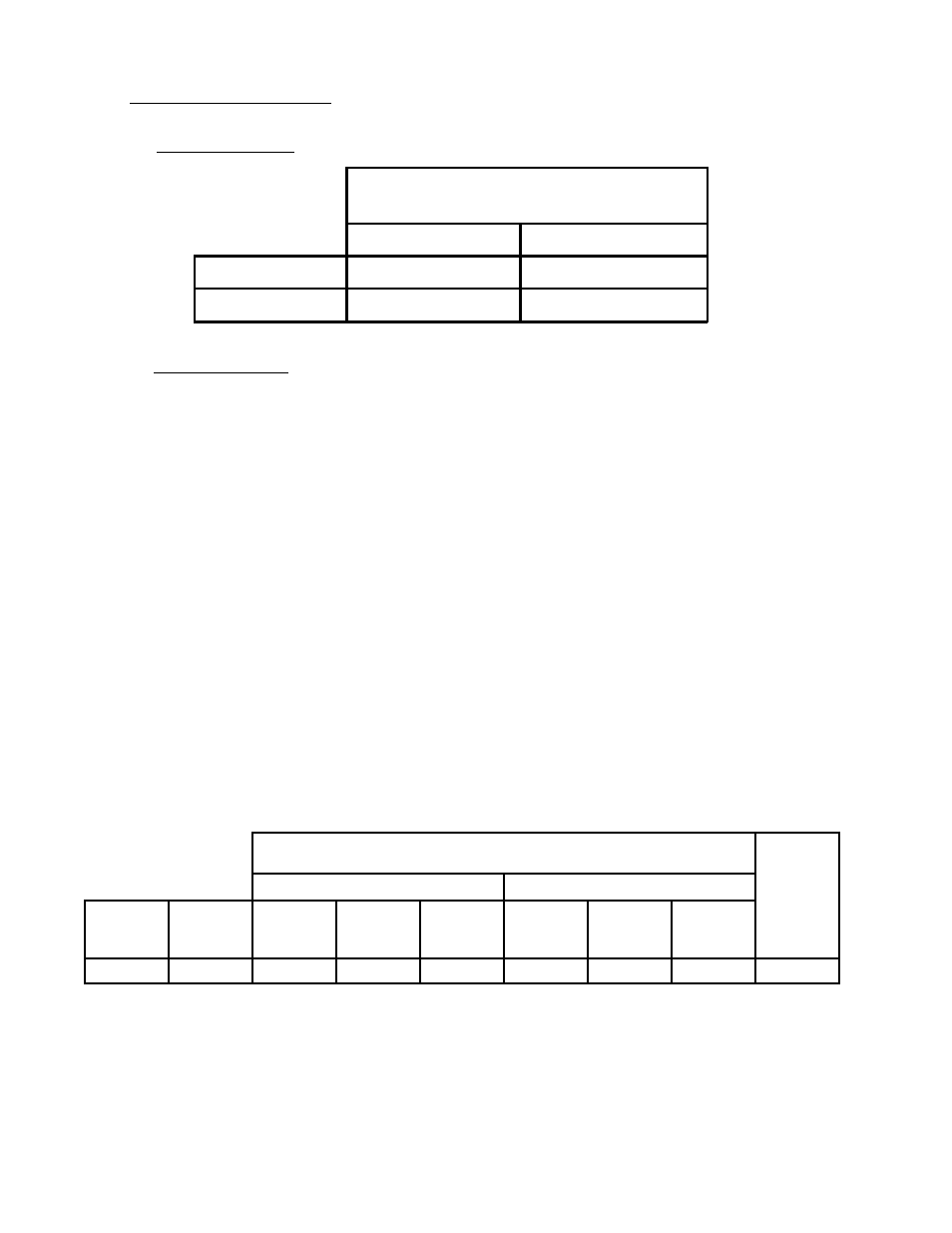
2. TECHNICAL GAS DATA
a. Gas Specifications
b. Gas Connections:
Inlet connection ------------ 3/4"-inch N.P.T.
Inlet supply size ------------ 3/4"-inch N.P.T. (minimum)
Btu/hr input (per dryer) --- 200,000
1) Natural Gas
Regulation is controlled by the dryer's gas valve's internal regulator. Incoming supply
pressure must be consistent between a minimum of 6.0 inches and a maximum of 12.0
inches water column pressure.
2) Liquid Propane (L.P.) Gas
Dryers made for use with L.P. gas have the gas valve's internal pressure regulator
blocked open so that the gas pressure must be regulated upstream of the dryer. The
pressure measured at each gas valve pressure tap must be a consistent 11.0 inches
water column. There is no regulator or regulation provided in an L.P. dryer. The water
column pressure must be regulated at the source (L.P. tank) or an external regulator
must be added to each dryer.
* D.M.S. (Drill Material Size of equivalents are as follows:)
Natural Gas ................... # H = .2660
Liquid Propane Gas ...... # 21 = .1590
7\SH RI *DV
1DWXUDO
/LTXLG 3URSDQH
0DQLIROG 3UHVVXUH
LQFKHV :&
LQFKHV :&
,QOLQH 3UHVVXUH
LQFKHV :&
LQFKHV :&
7\SH RI *DV
GQ
8r v
FvÃQh
Iir
1DWXUDO
/LTXLG 3URSDQH
Hqry
Iir
7UVÃQr
C
Shvt
R
9HT
Qh
Iir
R
9HT
Qh
Iir
69B&$
!
ЖC
# $"
Ж!
# $!
'&##!