48vdc powered transmitter hookup diagram – Nitek ER8500C User Manual
Page 7
Optional Hookup for High Power PoE Devices
ET1500C Units
In some cases the PoE device connected at the transmitter end needs more power than can be supported over a
long coaxial run. You can usually identify these cases by watching the POWER LED of the transmitter, located on
the “Network Port”. If the power light cycles ON for less then 1 second and then is off for 3 or 4 seconds when the
PoE device is connected, but it turns ON and operates normally without a PoE device connected, this would indi-
cate you are having a current limit problem.
You should first check the power requirements of the PoE device. Also check the length of the coaxial cable. The
POE POWER CHART on the previous page will indicate the maximum power available for your length of coax.
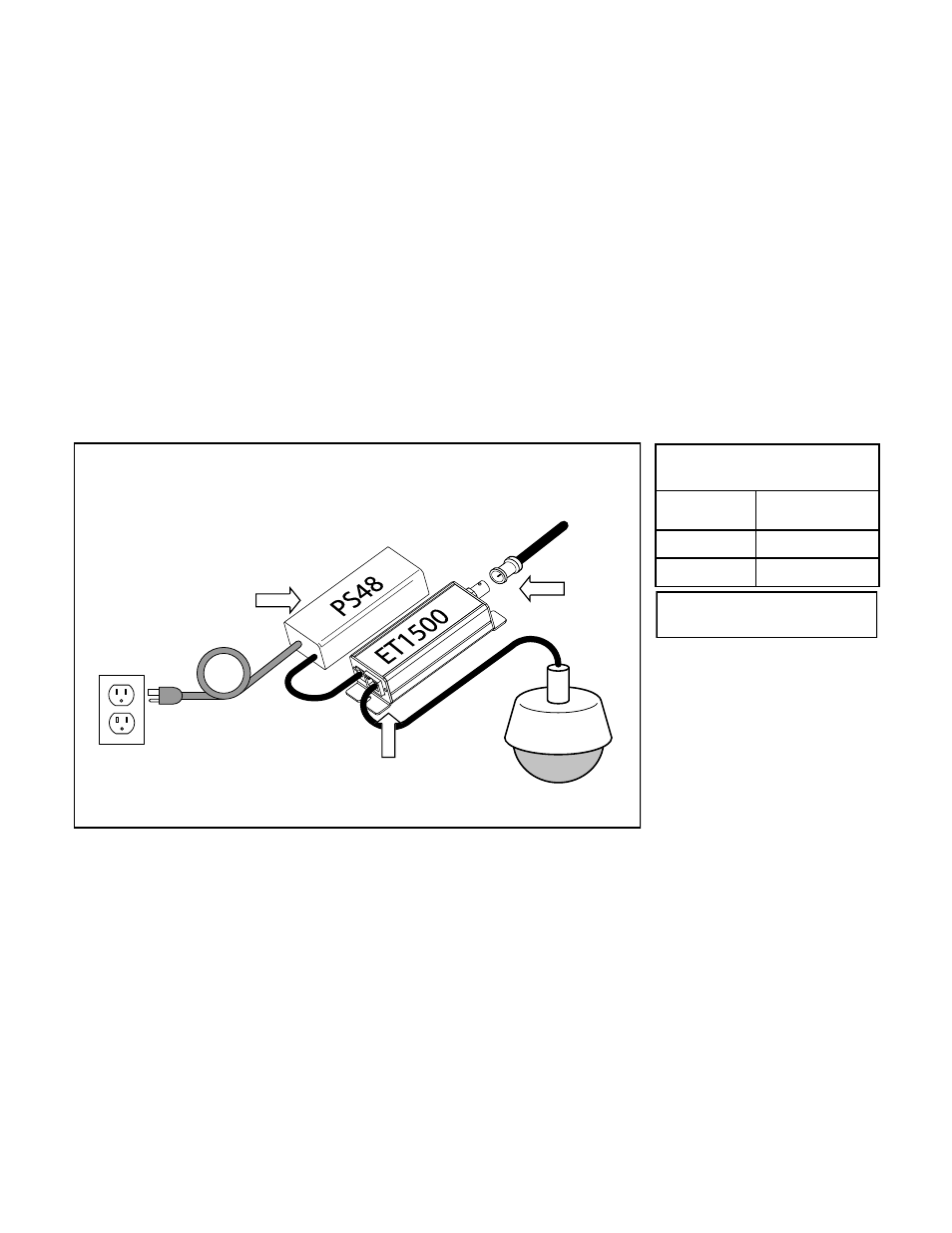
If the needed level of power is not available for the length of coaxial cable, alternate options are available. One
method is to directly power the transmitter with a 48VDC power supply as shown below (Nitek# PS48). When pow-
ered directly from a 48VDC supply the transmitter can deliver full 802.3AT power regardless of the coaxial cable
length plus an additional length of up to 100 meters of network cable.
Transmitter used as
PoE Injector*
Distance from
Network Port
PoE Device Power
Available
30ft/10m
33 watts
325ft/100m
26 watts
*
Results with 48VDC power to the
Transmitter optional Power Port
IP Camera
Coax from
Head-end
48VDC Powered Transmitter Hookup Diagram
Link Port
Network
Port
115 VAC
Optional
48VDC
Supply