Installation instructions, Troubleshooting, Typical hook-up – Nitek FSS20111S User Manual
Page 2
Installation Instructions
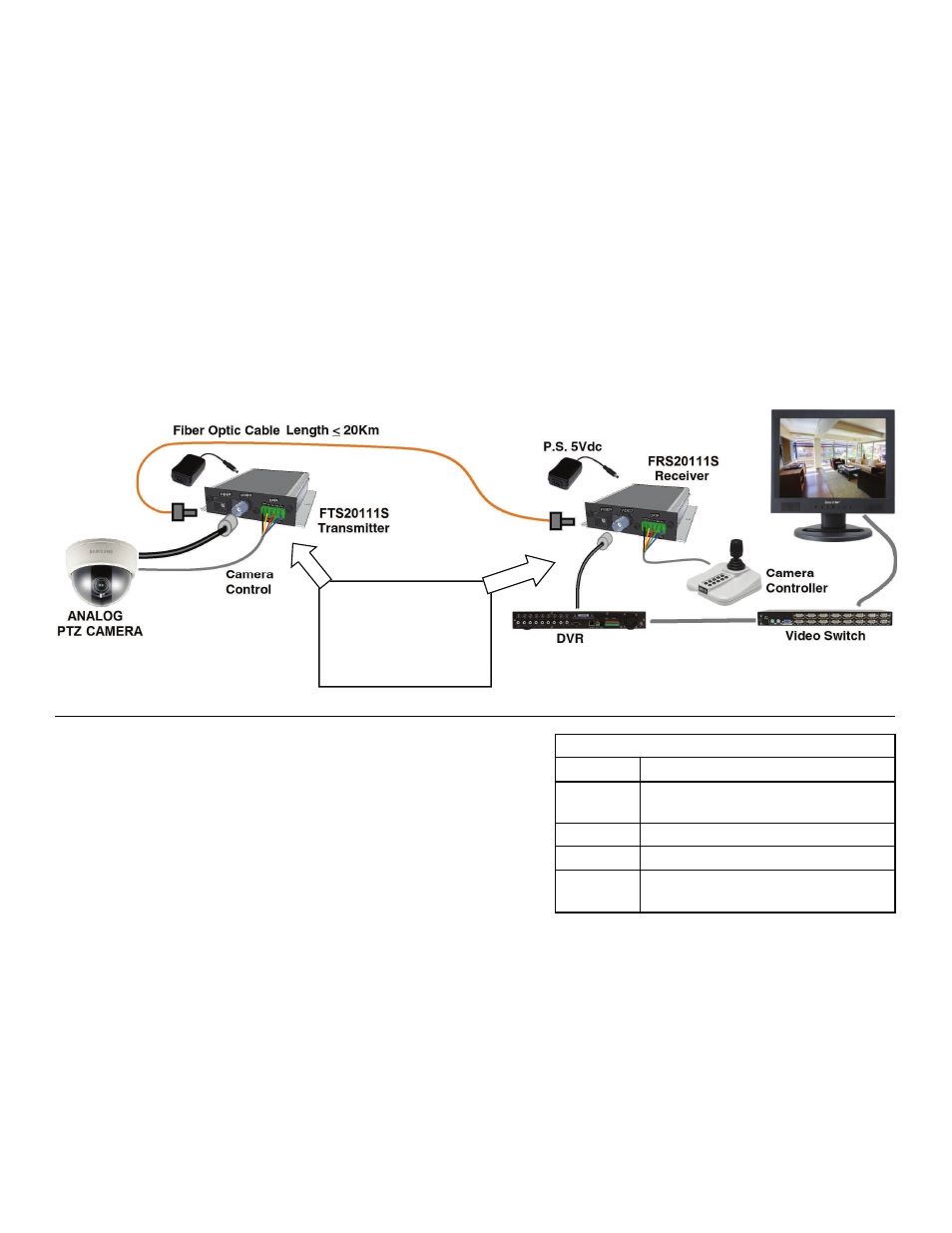
Refer to the previous diagram and the one below, use best industry practices and follow all local building codes.
1. The devices can be rack mounted or mounted on the wall. For wall mounting, use two appropriate screws to fix the
devices onto the wall. Make sure there is enough room for cable connections.
2. For use with the fiber rack mount chassis, remove the two Hex Head screws on the front of the unit and pull the card
unit out of the wall mount chassis. Please refer to the fiber chassis RS2020S for mounting instructions.
3. Connect fiber cable between the transmitter and the receiver using SC fiber connector.
4. Connect monitor and control panel to the video port and data port of receiver respectively.
5. Connect PTZ camera to the video port and data port of transmitter.
6. Connect the supplied power supply to the transmitter and the receiver.
Note there is no technical adjustment required during installation.
Troubleshooting
Problem: No video present
1. Is the Power LED in the device illuminated?
Answer — No
Check to insure power adapter is properly connected to the device
and power outlet.
Is the correct 5V DC adaptor that was supplied with the unit being
used?
Contact tech support at Nitek
2. Is the LED for fiber connection in the device FLASH?
Answer — Yes
Check the fiber connection to both transmitter and receiver.
Check the SC fiber connector on both transmitter and receiver is clean and properly connected to the fiber cable.
Contact tech support at Nitek
3. Is the LED for video connection in the device illuminated?
Answer — No
Check the camera for a video output.
Check the video cable connection between the camera and the transmitter and also the monitor and the receiver.
Check the BNC connector on both transmitter and receiver is clean and properly connected to the video cable.
Contact tech support at Nitek
LED INDICATORS
LED
STATUS
PWR
On - Normal Operation, unit powered-up
Off - Check power supply
VIDEO *
Glows - With Video Luminance
Tx
Blinks - Normal when data is transmitted
Rx
On - No Fiber Connection
Blinks - Normal when data is received
* Receiver Blinks rapidly with NO Fiber Connection
Data In and Out are
labeled for connection
type, i.e. Tx+ from
transmitter goes to the
Tx+ of the camera.
Typical Hook-up