Nitek FRS58110xR00 User Manual
Page 2
Power Requirements
Power (Stand Alone)
12VDC to 18VDC / 600mA
maximum
Front Panel Indicators
Opto LEDs
Primary
Opto
Green—transmitting
Off—not transmitting
Secondary Opto
Green—transmitting
(if equipped)
Off—not transmitting
Video LEDs
Video
Present
Green—video
present
Data LEDs
Channel A Data (if equipped)
Data Present TX
Green—data high
(RS485/RS422)
Red—data
zero
Off—tri-state
or
N/C
Data Present TX
(RS232) Green—data
high
Red—logic
transitions
Off—data
zero
Channel B Data (if equipped)
Data Present TX
Green—data high
Red—logic
transitions
Off—data
zero
Channel B Audio Data (if equipped)
Audio Present TX
Green—audio > -40dBm
Red—audio > 0dBm
(audio
overload
level+6dBm)
Off—audio
<
-40dBm
Data Connections
Data Connector
RJ45
No. of Channels
2
Channel A Interface
On Board Data Interface—RS232, RS422 or RS485.
(if equipped)
Selected by slide switch above RJ45 connector.
Channel B Interface
Defined by ACX Interface Board.
(if equipped)
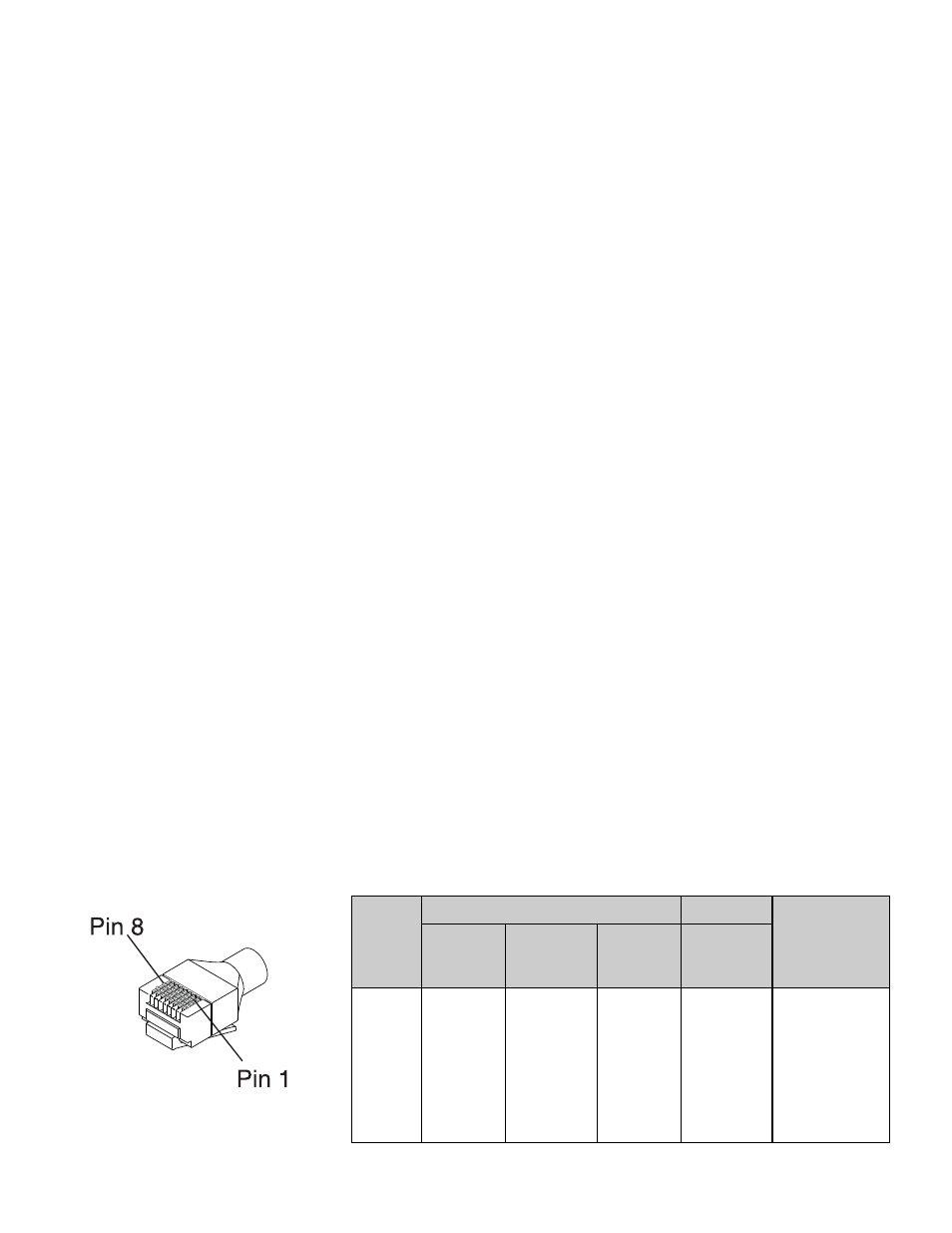
RJ45
Pin No.
Channel B
T568B Color
Code
Cat 5/6 cable
RS485
RS422
RS232
Data
Interface
Board
1
2
3
4
5
6
7
8
IN/OUT +
IN/OUT +
IN +
IN +
OUT +
OUT -
GND
IN
N/A
OUT
OUT +
IN -
IN +
OUT -
White/Orange
Orange
White/Green
Blue
White/Blue
Green
White/Brown
Brown
Channel A
RJ45 ACX Interface Connections
RJ45 Plug
Video Input Connections
Connector
75 ohm BNC socket
Input Impedance
75 ohm terminated
Input Level
1 volt p-p nominal
Frequency Response
10Hz to 5.75MHz
Fiber Connections
Primary
OPTO
Out
Connector
LC/PC
Primary Optical Out Power
-5dBm
Wavelength
1310nm
Optical Fiber
Single-Mode
Primary OPTO In
Connector
LC/PC
Primary Optical Sensitivity
-22dBm
Wavelength
1310nm
Optical Fiber
Single-Mode
Audio Connections
Input Impedance
600 ohm
Output Impedance
600 ohm
Auxiliary Ports
Alarm In
Contact Closure
Alarm Out
100V / 150mA max.
Ethernet Option
If equipped, RJ45 will
(if
equipped)
LED
indicators.
This is a
standard
10/100 Ethernet
port.