Installation & setup, Hook-up – Nitek VB39M User Manual
Page 4
Installation & Setup
Unshielded Twisted Pair
(Loop Resistance at 750 feet)
AWG
18
20
22
24
Loop Resistance
10 Ohms
15 Ohms
24 Ohms
39 Ohms
Mounting
The VB39M can be mounted external to a camera housing by use of the mounting leg, or can
be placed inside the camera housing.
When mounting the VB39M externally, the placement should be sufficiently close to the camera
housing so that the coax cable from the camera can be conveniently connected to the VB39M.
The mounting leg of the VB39M can be used to secure the device either with a screw or wire
wrap. The wires of the UTP cable must be stripped, as required and wrapped around and con-
nected to the appropriate
+
and
-
Screw terminals on the back of the VB39M. Be sure to main-
tain the same UTP polarity at both the transmit and receive units.
When mounting the VB39M inside a camera housing a small hole must be available to pass
the UTP cable through. The cable must be of sufficient length to be routed back to the video
crossover. As with external mounting, the coax video cable will connect within the housing to
the camera video BNC input.
In either mounting, connect an 18 AWG solid wire from Earth Ground to the “Ground” terminal
on the VB39M for optimum surge protection.
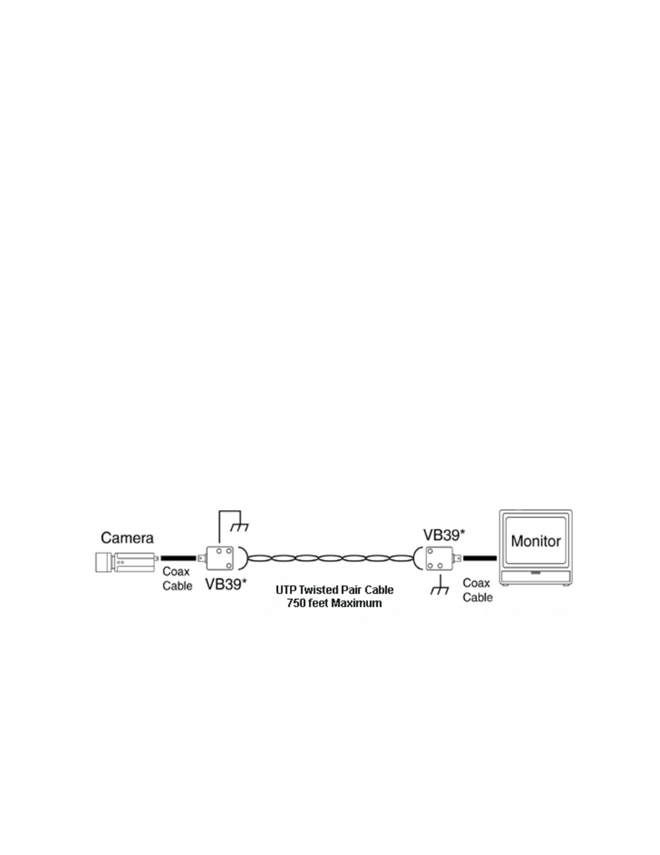
Hook-Up
In the diagram shown above, two VB39M devices are used; one at the Head-End (monitor loca-
tion) and the second at the camera location. No voltage is required for the baluns, since they are
passive devices. Video is sent back to the monitor over the UTP cable by means of the two
baluns operating as video transceivers. Note the Earth Ground connections for the surge protec-
tion circuits.