Nitek, Tr560x8 card, Installation instructions – Nitek VH3256 User Manual
Page 3: Specifications, Determining cable length
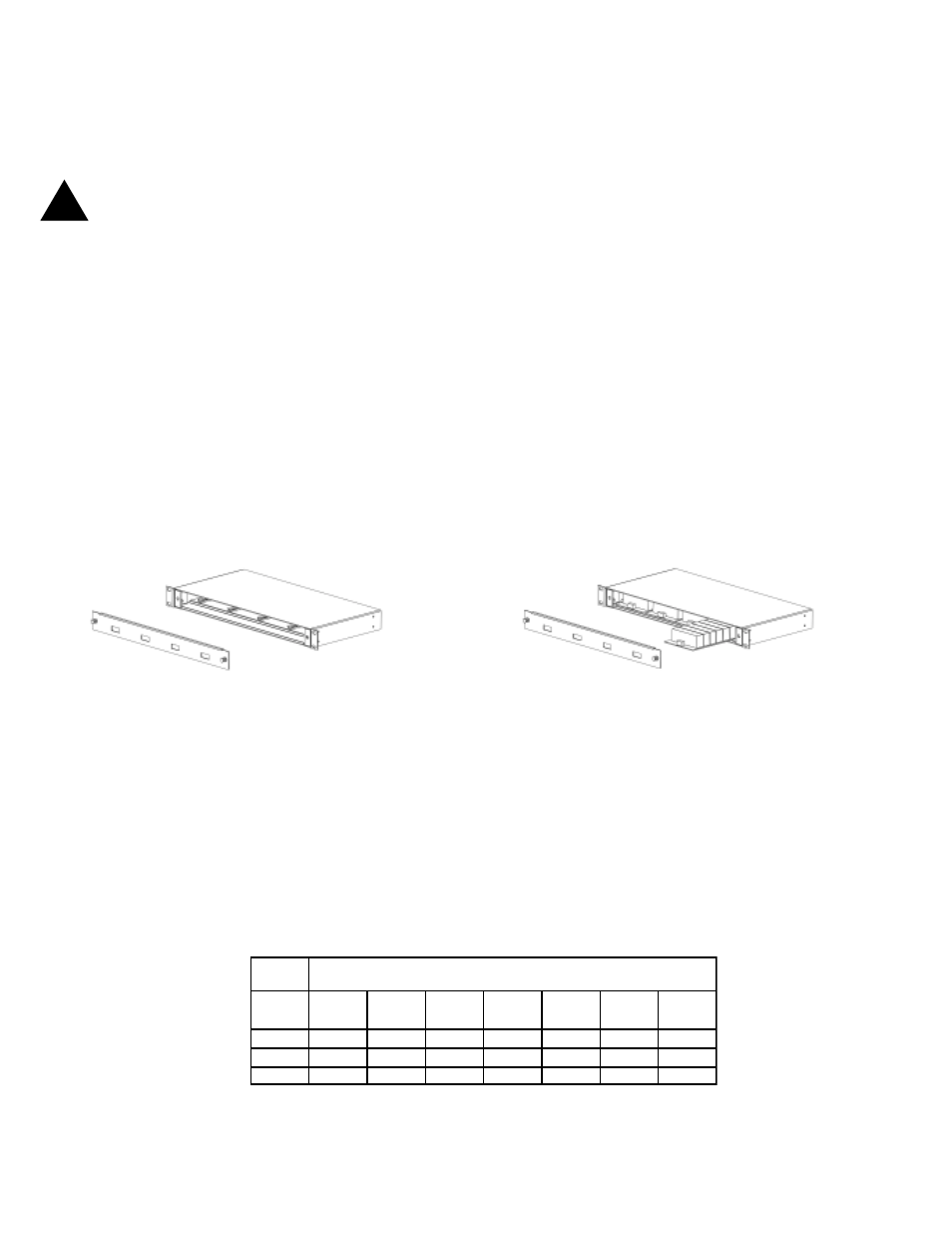
Remove front panel
Install cards
5410 Newport Drive, Suite 24
Rolling Meadows, IL 60008
PHONE (847) 259-8900
FAX (847) 259-1300
Internet: www.nitek.net
NITEK
®
Installation Instructions
TR560x8 Card
Note: This installation should be made by a qualified
service person and conform with local codes.
!!!!!
Reduce risk of fire or electrical shock do
not expose this product to rain or moisture.
Specifications
Power Requirements: Power is supplied by VH3200
UTP Wire Length:
up to 3000 feet with passive transmitter
up to 6000 feet when used with active transmitter
This sheet is designed to cover TR560x8 receiver card UTP video system. This sheet is divided into
two sections. First is the TR560x8 card used with a passive (balun) transmitter. Second is the TR560x8
card used with an active (TT560) transmitter.
To install the TR560x8, remove the front panel of the VH3200 Modular Hub by pulling on the two front
panel knobs. Insert the card into any open slot. Replace the front cover and press the knob in to lock it
in place.
Rev 091003
E
R
I
W
E
G
A
G
)
S
R
E
T
E
M
(
T
E
E
F
N
I
E
C
N
A
T
S
I
D
0
0
5
)
2
5
1
(
0
0
0
,
1
)
4
0
3
(
0
0
0
,
2
)
0
1
6
(
0
0
0
,
3
)
4
1
9
(
0
0
0
,
4
)
9
1
2
1
(
0
0
0
,
5
)
4
2
5
1
(
0
0
0
,
6
)
9
2
8
1
(
2
2
6
1
2
3
4
6
7
9
9
2
1
1
6
1
4
9
1
4
2
6
2
1
5
3
0
1
4
5
1
5
0
2
7
5
2
8
0
3
6
2
1
4
2
8
3
6
1
5
4
2
6
2
3
8
0
4
0
9
4
Determining Cable Length
Check the twisted pair for continuity. Do this by shorting the pair of wires at one end and use an ohm meter to check
the resistance at the other end. Use the chart below to determine the length of your wires for a measured
resistance. Also, use the multimeter to test the line and make sure there is no voltage on it. Testing each line and
recording the length for each camera run can greatly reduce installation time. For distances greater than 3,000
feet an amplified transmit source may be needed.