Nitek, Dc b a, Installation – Nitek PVR164 User Manual
Page 2: Front panel connections back panel connections, 568b, Standard system hookup, Cables, Front view back view, Utp video system
VB43ATF
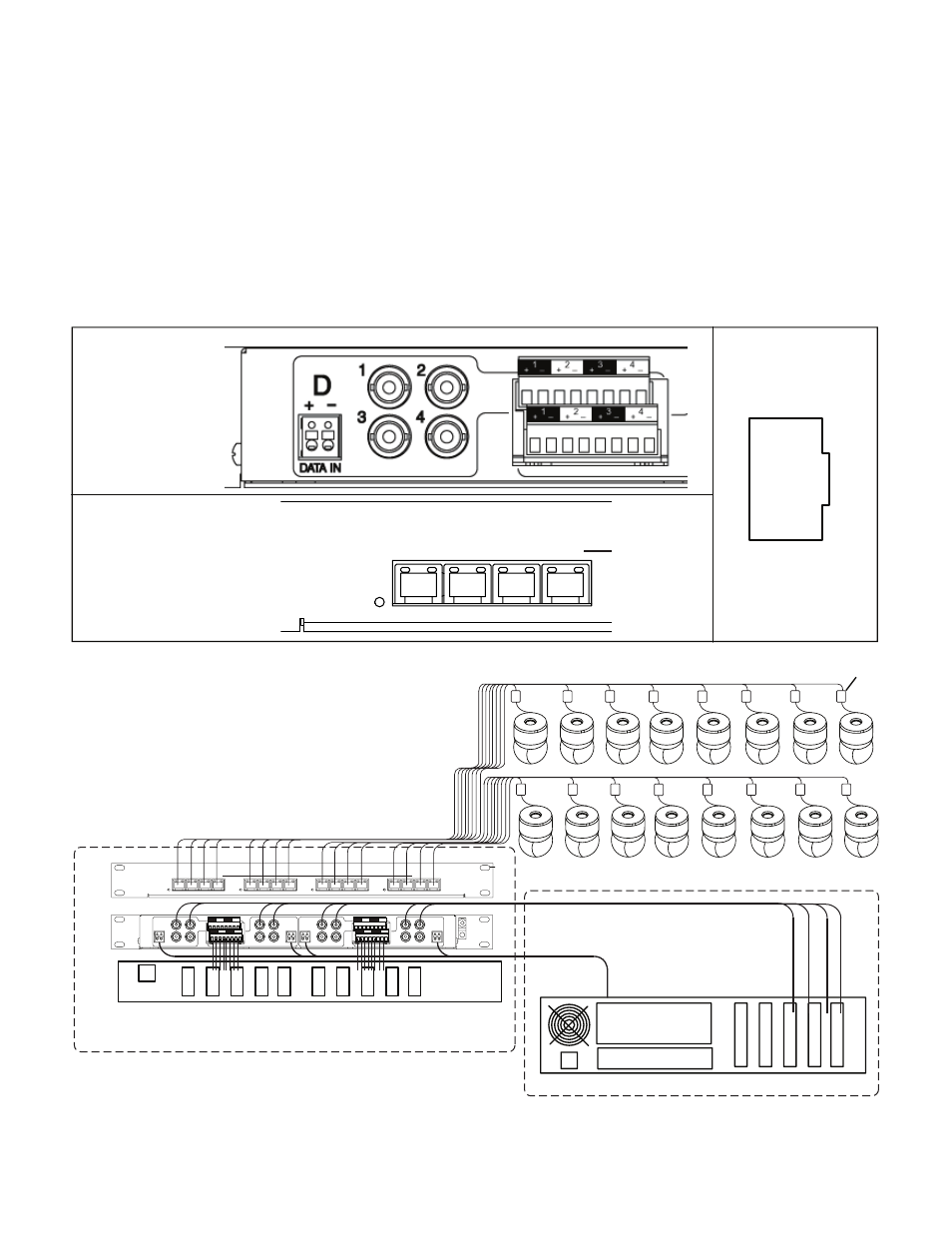
Rackmount 16 port Class 2 SELV Power Supply
DVR
Cables
4-pair Category Cables
Wiring / IDF Telecom Closet
Control Room / MDF
Video
Data
Front
View
Back
View
Video, Power, and Data
1
2
3
4
DATA
DATA
DATA
DATA
1
2
3
4
1
2
3
4
1
2
3
4
PVR164 UTP VIDEO HUB
NITEK
UTP Video System
A
B
C
D
1
2
3
4
DATA IN
DATA IN
D
C
B
A
+
-
DATA IN
DATA IN
DATA IN
DATA IN
DATA IN
DATA IN
+
-
+
-
+
-
1
2
3
4
1
2
3
4
1
2
3
4
1
3
+ -
+ -
+ -
+ -
2
4
1
3
+ -
+ -
+ -
+ -
2
4
1
3
+ -
+ -
+ -
+ -
2
4
1
3
+ -
+ -
+ -
+ -
2
4
Installation
Rear Panel Connections
1. BNC jacks are video out ports. Connect to DVR unit or other video display. A green LED will light on the RJ45
port to indicate the presence of video.
2. Control data is connected to the push-in terminals marked “DATA IN”. An amber LED on the front panel will
light or flash to indicate data is passing through the ports.
3. Power for each camera port is marked “+” or “-” for DC power. AC power can be connected to either terminals.
A red LED will indicate power is present on the RJ45 port.
Front Panel Connections
1. There is one RJ45 port pr camera. This port combines all of the signals needed for the CCTV camera into one
cable, which should be wired using the 568B standard on both ends.
Front Panel
Connections
Back Panel
Connections
8 + Power
7 - Power
6 + Power
5 + Data
4 - Data
3 - Power
2 - Video
1 + Video
568B
1
2
3
4
DATA
NITEK
UTP Video System
A
1
2
3
4
DATA IN
D
C
B
A
+
-
DATA IN
DATA IN
DATA IN
+
-
+
-
+
-
1
2
3
4
1
2
3
4
1
2
3
4
Standard System Hookup