40’ gabled navi-trac frame terminology – Anchor Industries NAVI-TRAC NAV40GBL-1104 User Manual
Page 3
3
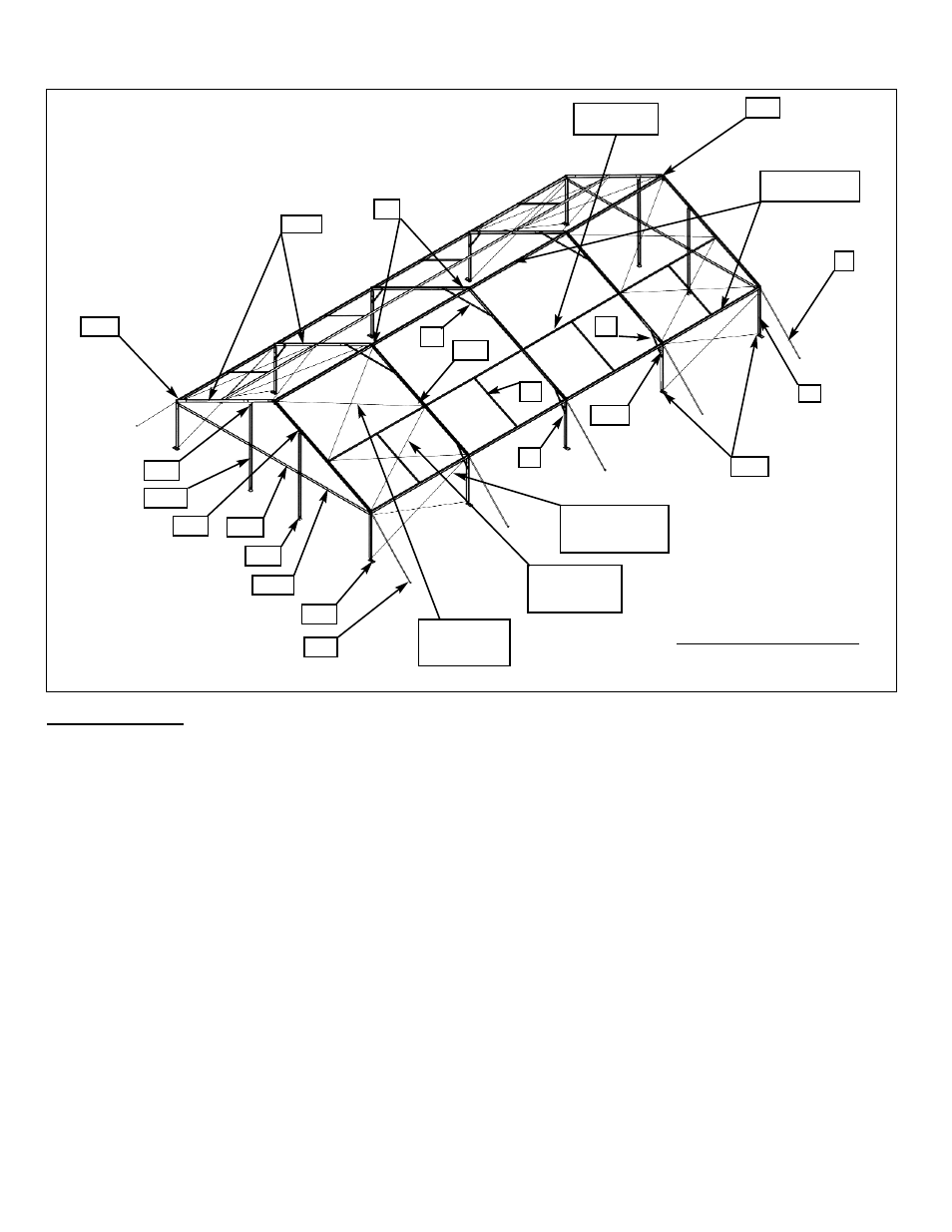
40’ Gabled Navi-Trac Frame Terminology
INTRODUCTION:
Like the hip-end version, the gabled end NAVI-TRAC frame is made up of extruded aluminum members joined
by weldments. The aluminum frame members themselves are extruded with channels into which the NAVI-
TRAC fabric “kedar” is fed. However, the gabled end version of the Navi-Trac differs from the Hip End version
in a number of ways:
1. All the beams are parallel to each other.
2. Beam base plates are hinged for pivoting to a vertical position. End Upright plates are fixed, non-pivoting.
3. The eave fittings are the MCW style that allows a simple drop-in action for purlin installation, rather
than the slip joint of the hip end configuration.
4. Fabric middle bays are installed into the channels of adjacent beams one bay at a time.
5. Gabled End fabric is intalled simply into the outer channel of the end beams and tensioned to the
Gabled End uprights.
6. X-Cabling extends into the overhead rafter area to compensate for the lack of hip end support.
7. Corner guys are in one direction only, parallel to the beams.
It is possible to combine the hip end and gabled end styles within one building unit (see kit #3); however
this assembly manual focuses on the gabled end configuration only. The last few pages describe the
hip/gabled combination and refer the customer to the hip end assembly manual for the hip end part of
the building unit.
R21-9
P1, P2 OR P3
(OPTIONAL)
U8
BHW
RWE
RW
G
T-42
X-4, 5 or 6
(OPTIONAL
BAY SPACING)
X-1, 2 or 3
(OPTIONAL BAY
SPACING
MCW
X-7, 8 or 9
(OPTIONAL
BAY SPACING)
EE10
ER10, 15, 0R 20
(OPTIONAL)
BFW
T-30
EW15
U8
XRB
MCW
B3
UGT
UG-15
GRW
P1
B4
See Component List Table on
Pages 5 & 6 for component
descriptions.