7 rs-485 wiring, Device board terminals – DoorKing 1838 Telephone Access Plus User Manual
Page 14
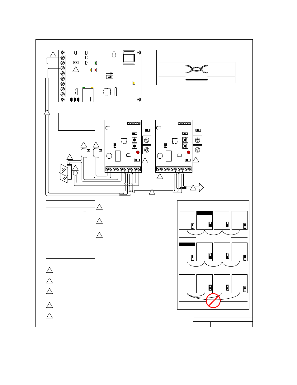
1.7 RS-485
Wiring
Device 1
Address 003
Device 2
Address 004
3
5
2
6
3
5
2
6
1
1
6
12 – 24 Volt, AC or DC power. Do not power
Device board(s) from 1838 Unit. They must be
supplied with their own power source as shown .
Lock power. Do not power magnetic locks or electric strikes from the device circuit
board power source. Locks must be powered from their own source .
Magnetic locks are wired to the Normally Closed relay
contacts. Electric strikes are wired to the Normally
Open relay contacts.
SW 5 is in the OFF position for middle units, and in the ON position for end units. If
terminals 6, 7 & 8 have two wires connected to them, the SW 5 must be OFF. If terminals 6,
7 & 8 have only a single wire connected, the SW 5 must be ON.
7
7
Maximum distance from end to end is 4000 feet in a Daisy Chain format as shown in the
diagram at right.
Exit
Note RS485 ‘Daisy Chain’ wiring. Controller does
not need to be on the end.
ON
Address 004
End Units
SW 5 ON
Address 003
OFF
Middle Units
SW 5 OFF
ON
Address 005
End Units
SW 5 ON
ON
Address 005
End Units
SW 5 ON
OFF
Address 004
Middle Units
SW 5 OFF
Address 003
OFF
Middle Units
SW 5 OFF
Access Plus
Controller
ON
Address 005
End Units
SW 5 ON
OFF
Address 004
Middle Units
SW 5 OFF
Address 003
OFF
Middle Units
SW 5 OFF
Correct – 4000 Ft. Max.
Correct – 4000 Ft. Max.
A switch closure across the device board terminals 9 & 10 will activate the device
(card reader, keypad, RF receiver) relay for its programmed strike time.
4
4
SW
3
SW2
SW
4
11
12
13
16 15 14
17
1
2
3
4
5
6
7
8
9
10
OFF
SW5
The wires connected from the 1838 RS-485 board
(terminals1 & 2) to the Device boards (terminals 8 & 7)
MUST be twisted. We recommend that you use
Cat5e cable. Use one pair to these terminals and
then one wire from one of the other pairs to connect
terminal 6. If wiring will be outdoors or underground,
use Cat5e Gel Filled (flooded) UV Resistant Direct
Burial Cable. Match terminals on RS 485 board (i.e.,
term 6 to term 6; term 7 to term 7; term 8 to term 8).
1
2
3
4
5
6
7 8
9
0
SW2
OF
F
SW4
S
W3
1
2
3
4
5
6
7 8
9
0
SW
3
1
2
3
4
5
6
7 8
9
0
1
2
3
4
5
6
7 8
9
0
SW2
OF
F
SW4
1
Incorrect
ON
SW1
MODEM / TCP ENB
1
2
3
4
5
6
7
8
BAD DNS
RS-485 RX
LAN DOWN
Phone Line In
Use
L
AN Conn
ect
ion
Dat
a
T
ran
smi
t
To “Devices” 3-4-5-6;
addresses 005, 006, 007 , 008.
3
RS-485 Board
Terminal 1 from the 1838 RS-485 board connects to Device board(s) terminal 8.
Terminal 2 from the 1838 RS-485 board connects to Device board(s) terminal 7.
Terminal 3 from the 1838 RS-485 board connects to Device board(s) terminal 6.
Wires connecting terminals 1 & 2 to terminals 8 & 7 MUST be twisted.
Term 8
RS-485 Data A (+)
Term 6
RS-485 Common
Term 7
RS-485 Data B ( - )
Term 1
RS-485 Data A ( + )
Term 2
RS-485 Data B ( - )
Term 3
RS-485 Common
RS-485 Board
Device Board
RS-485 Terminal Connections
1 12-24 V AC/DC Input ( )
2 12-24 V AC/DC Input ( )
3 Relay Normally Open (N.O.)
4 Relay Normally Closed (N.C.)
5 Relay Common
6 RS485 Gnd
7 RS485 Data (B)
8 RS485 Data (A)
9 Request to Exit Com
10 Request to Exit Input
Device Board Terminals
NOTE:
“Devices” can be card
readers, keypads or RF
receivers
SW
3
SW2
SW
4
11
12
13
16 15 14
17
1
2
3
4
5
6
7
8
9
10
OFF
SW5
RS-485 Device Connections
DOORKING, INC., INGLEWOOD, CA 90301
Date:
Dwg. No.
Rev.
Title:
1/12
C
1838-003-C
3
SW2
ON
TERMINATION
OFF
AP Controller
OFF
Middle Unit
SW 2 OFF
ON
AP Controller
End Unit
SW 2 ON
8
If the AP Controller is an END unit, then SW 2 is ON. If the AP Controller is a middle unit,
then SW 2 is OFF.
8
Page 14
1838-066-D-1-12