2 phone line polarity, Fiber / v olp device, Homeowner’s phones – DoorKing 1812 Access Plus User Manual
Page 49
1812-162-M-1-12
47
EARTH
GND
SW1
ENTRY BY-PASS
1875-010
1
CENTRAL
OFFICE
PHONE
IN
PHONE
OUT
HOME
2
3
4
5
6
7
8
TIP
TIP
TIP
RING
RING
RING
TIP
RING
EARTH
GND
SW1
ENTRY BY-PASS
1875-010
1
CENTRAL
OFFICE
PHONE
IN
PHONE
OUT
HOME
2
3
4
5
6
7
8
TIP
TIP
TIP
RING
RING
RING
TIP
RING
77
8
9
4
5
6
1
2
3
0
1111
2222
333333
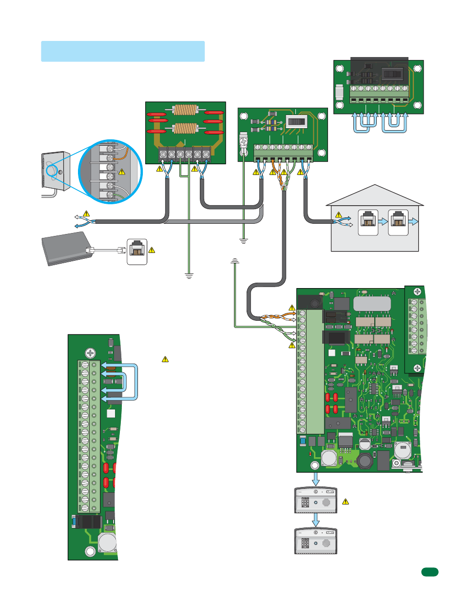
When troubleshooting 1812 operational problems, check
phone line polarity. Crossed polarities can affect system
operation.
Main Terminal - Circuit board
connections are shown for
clarification purposes. DO NOT
add any additional jumpers to
wiring or terminals.
By-Pass Board - Circuit board
connections are shown for
clarification purposes. DO NOT
add any additional jumpers to
wiring or terminals.
Check Polarity on Terminals
Example: set a VOM meter to measure
DC volts. Place the positive lead on 1812
terminal 2 and the negative lead on 1812
terminal 1. If the meter shows a positive
voltage - OK. If the meter shows a
negative voltage (needle moves off scale
to the left), reverse the wires. Repeat this
process to check other wire pairs on
bypass board and 1812 main terminal.
5.2 Phone Line Polarity
J1
1
2
3
4
5
6
7
8
J4
INPUT
PHONE LINE
TIP
RING
1877-010
OUTPUT
TIP
RING GND GND
Phone
Jack
Phone
Jack
Cat5e
Cat5e Without Surge Board
Cat5e
Cat5e
To
Surge Board
Cat5e
Homeowner’s Phones
Check that all boards
are properly grounded
with 12 AWG gauge
wire minimum.
By-Pass Board
PHONE IN #3 - DC Negative.
PHONE IN #4 - DC Positive.
PHONE OUT #5 - DC Positive.
PHONE OUT #6 - DC Negative.
Main Terminal
PHONE IN #1 - DC Negative.
PHONE IN #2 - DC Positive.
PHONE OUT #4 - DC Positive.
PHONE OUT #5 - DC Negative.
Phone Line Surge Suppressor
J1
Main
Terminal
TIP
Older Lines
Green Wire (+)
Older Lines
Red Wire (-)
RING
1970-010
18
17
16
15
14
13
12
11
10
9
8
7
6
5
RING
4
TIP
3
GND
2
TIP
1
RING
When multiple 1812
systems are connected
together, maintain
common polarity on
ALL phone lines.
7
8
9
4
5
6
1
2
3
0
1111
2222
333333
J1
1970-010
18
17
16
15
14
13
12
11
10
9
8
7
6
5
4
3
2
1
DC Negative
DC Negative
DC Positive
DC Positive
SW
W
ENTRY
ENTRY BY-PAS
BY-PAS
DC Negative
DC Positive
DC Positive
DC Positive
DC Positive
DC Negative
DC Negative
DC Negative
Ground
12 AWG
Min.
Ground
12 AWG Min.
Orange
Pair
Orange
Pair
Green
Pair
Green Pair
12 A
WG Min.
Within 3 ft of
Surge Board
Phone In
(1-2)
Phone Out
(4-5)
Main
Terminal
Central Office
Phone Line Inside Device
Phone at
Home #12
Phone at
Home #11
Phone at
Home #13
Tip
Ring
Tip
Ring
Tip
Ring
Telephone
Company
Demarcation
Point
Central Office (C.O.)
Demarcation Device
TIP (+): White/blue mark
RING (-): Blue/white mark
Fiber / V
olP
Device
RJ11
Phone
Connector
Phone
Jack
Internet
OR
OV