Remove the control board, Warning – DoorKing 1812 Access Plus User Manual
Page 10
1812-162-M-1-12
8
SECTION 1 - INSTALLATION
Installation of the 1812 Access Plus Telephone Entry System involves the installation of the hardware, by-pass board, and the
wiring of these components. Be sure that all dirt, metal or wood debris is removed from inside after mounting it. Any debris
inside could damage the control board and cause the 1812 Access Plus system to malfunction during operation.
Use the specification dimensions on pages 2 and 3 to help with the installation of your chosen 1812 Access Plus model.
When the 1812 Access Plus is used to control a vehicular gate with an automatic gate operator, it must be
mounted a minimum of ten (10) feet away from the gate and gate operator, or in such a way that a person
cannot operate the 1812 Access Plus system and/or touch the gate or gate operator at the same time.
1.1 Mount the 1812 Access Plus
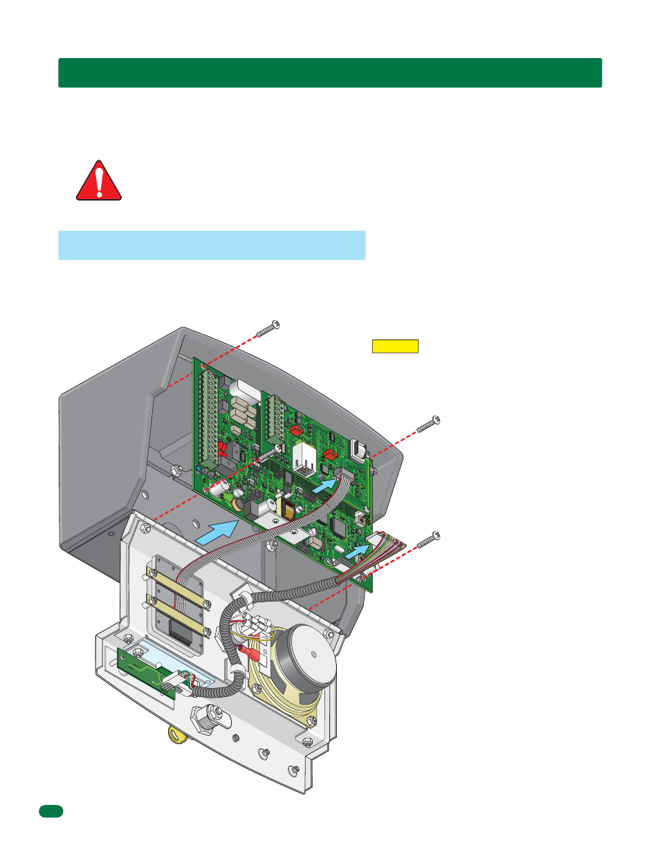
The control board removal is the same for all models.
1. Unlock and open the 1812 door.
2. Disconnect the keypad plug and
door accessories plug from the
control
board.
3. Remove the 4 screws.
Carefully remove control board.
Keep the control board in a
protected area during the mounting
installation.
CAUTION The control board contains static sensitive
components. Discharge any static electricity from
your hands by touching a proper ground device
before removing the control board.
Remove the Control Board
WARNING
SPE
AKE
R
VOL
MIC
VO
L
KEY
PAD
OV
MA
STER
CODE
1970-
010
18
11
1 2
3 4
5 6
7 8
910
17
16
15
14
13
12
11
10
9
8
7
6
5
4
3
2
1
J2
J1
J3
J3
J
MODEM
1972-
010
SW1
1
2
3
4
5
6
7
8
BAD
DNS
LAN
DOWN
RS-
485
RX
J4
ON
J1
RJ-45
Jack
(Cat5)
SW2
ON