1 device, 2 devices “daisy chain, 6 devices “daisy chain – DoorKing 1812 Access Plus User Manual
Page 23: 2 devices, 3 devices “daisy chain” 2 devices “daisy chain, 5 devices “daisy chain
1812-162-M-1-12
21
ON
ON
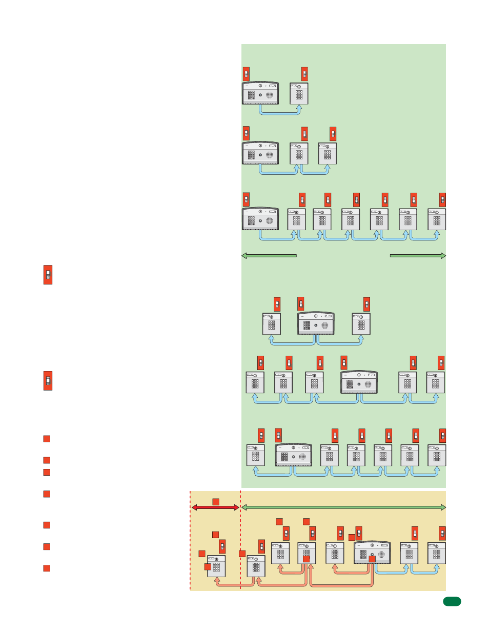
RS-485 Configurations
Device Address
Device Termination Switch
4000 ft Maximum (3/4 Mile)
CORRECT Configuration Samples
INCORRECT Configuration
1 Device
77
8
9
4
5
6
1
2
3
0
ON
ON
SW2
Terminated
Device
Address
003
Term Sw
Term Sw
Internal Addresses
001 for Relay 1
002 for Relay 2
(Factory Set)
2 Devices “Daisy Chain”
7
8
9
4
5
6
1
2
3
0
OFF
Address
003
Term Sw
ON
Terminated
End Device
Address
004
Term Sw
Internal Addresses
001 for Relay 1
002 for Relay 2
(Factory Set)
6 Devices “Daisy Chain”
7
8
9
4
5
6
1
2
3
0
OFF
Address
003
Term Sw
OFF
Address
004
Term Sw
OFF
Address
005
Term Sw
OFF
Address
006
Term Sw
OFF
Address
007
Term Sw
Terminated
End Device
ON
Address
008
Term Sw
Internal Addresses
001 for Relay 1
002 for Relay 2
(Factory Set)
2 Devices
ON
Terminated
Device
Address
003
Term Sw
ON
Terminated
Device
Address
004
Term Sw
3 Devices “Daisy Chain”
2 Devices “Daisy Chain”
OFF
Address
003
Term Sw
OFF
Address
006
Term Sw
OFF
Address
005
Term Sw
ON
Terminated
End Device
Address
004
Term Sw
ON
Terminated
End Device
Address
007
Term Sw
1 Device
ON
Terminated
Device
Address
008
Term Sw
5 Devices “Daisy Chain”
OFF
Address
003
Term Sw
OFF
Address
004
Term Sw
OFF
Address
005
Term Sw
OFF
Address
006
Term Sw
Terminated
End Device
ON
Address
007
Term Sw
1
ON
Terminated
Device
Address
005
Term Sw
2 Devices “Daisy Chain”
OFF
Address
004
Term Sw
Address
008
Term Sw
OFF
Address
003
Term Sw
Address
003
Term Sw
Terminated
End Device
ON
Address
004
Term Sw
ON
Address
007
Term Sw
7
8
9
4
5
6
1
2
3
0
Internal Addresses
001 for Relay 1
002 for Relay 2
(Factory Set)
Maximum of two (2)
terminated end
devices allowed.
Maximum of six (6)
devices allowed.
Any RS-485 Keypad,
Card Reader and
MicroPlus RF Receiver
sequence allowed.
A single “Daisy Chain”
wiring sequence has
the strongest signal
strength.
The 1812 system does not have to be a single “Daisy Chain” wiring sequence. What is
important is that the distance restriction (4000 ft) be observed and that the devices at the
end of the chain have their termination switch turned ON and the 1812 SW2 termination
switch turned OFF.
Every RS-485 device (keypad, card reader, MicroPlus RF
receiver) must have a unique address assigned to it,
starting with 003. The address selector switches are
located on the RS-485 circuit board (see instruction sheets
that come with each RS-485 device). The address order of
the devices connected to the 1812 does not matter. What is
important is that the addresses must be numbered in
sequence. Do not skip a number in the address sequence
and start the sequence with 003
(e.g. If three (3) RS-485 devices are daisy chain wired to
the 1812 and their addresses are 003, 004 and 006, this is
wrong. They must be addressed 003, 004 and 005).
The 2 internal relays on the 1812 circuit board are 001 and
002. Valid RS-485 external device addresses for use with
the 1812 Access Plus system are 003, 004, 005, 006,
007 and 008.
Important Note: The device address is referred to as a
“Relay Number” in the programming software.
A termination switch is located on every RS-485 circuit
board. The termination switch must be turned OFF for
every device wired in a daisy chain except for the last
device. It must have it’s termination switch turned ON.
A single RS-485 device wired to the 1812 must have it’s
termination switch turned ON. A maximum of 2 devices or
2 daisy chains can be individually wired to a single 1812
(Only 2 terminated devices allowed).
Single run (Daisy chain) of RS-485 devices. SW2 ON.
Runs in two different directions of RS-485 devices. SW2 OFF.
Some Configuration Problems to Avoid:
The total distance for the complete wire
run is greater than 4000 ft.
There are more than 6 RS-485 devices.
There are more than 2 wire runs coming
out of the 1812.
There are more than 2 end devices
terminated and/or incorrect end device
terminations (Not turned ON).
There are more than 6 addresses and/or
duplicate or skipped addresses.
An RS-485 device can not have 2 RS-485
devices separately continued from it.
The 1812 must have it’s SW2 termination
switch turned OFF when 2 terminated end
devices are being used.
2
3
1
2
3
4
4
4
4
5
5
5
6
7
6
7
ON
1812 SW2 Termination Switch
ON
SW2
ON
SW2
Term Sw
ON
SW2
Term Sw
7
8
9
4
5
6
1
2
3
0
Internal Addresses
001 for Relay 1
002 for Relay 2
(Factory Set)
OFF
SW2
W2
Term Sw
7
8
9
4
5
6
1
2
3
0
Internal Addresses
001 for Relay 1
002 for Relay 2
(Factory Set)
OFF
SW2
W2
Term Sw
7
8
9
4
5
6
1
2
3
0
Internal Addresses
001 for Relay 1
002 for Relay 2
(Factory Set)
OFF
SW2
W2
Term Sw
ON
SW2
Term Sw