DoorKing 1812 Access Plus User Manual
Page 21
1812-162-M-1-12
19
J1
1
2
3
4
5
6
7
8
J4
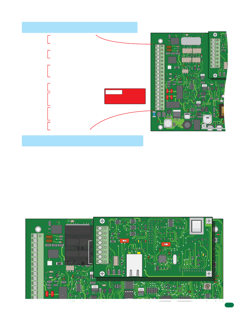
1.11 Main Terminal Description
1.12 Access Plus Interface Board
1970-010
Phone In
(Twisted Pair)
Phone Out
(Twisted Pair)
Relay 1
(Access Control Device)
Relay 2
(Access Control Device)
Input Power
(Transformer)
Back-Up
Battery Power
Emergency
and/or Postal
Entry Switch
1. Phone In (Negative - Ring)
2. Phone In (Positive - Tip)
3. Ground
(Required)
4. Phone Out (Positive - Tip)
5. Phone Out (Negative - Ring)
6. Not
Used.
7. Switch Input Relay 1. A switch closure across terminals 7 & 9
will activate relay 1 for its programmed strike time.
8. Switch Input Relay 2. A switch closure across terminals 8 & 9
will activate relay 2 for its programmed strike time.
9. - 12 VDC Battery Negative. Also Common for terminals 7 & 8.
10. + 12 VDC Battery Positive.
11. Relay 1 Normally Open
12. Relay 1 Normally Closed
13. Relay 1 Common
14. Relay 2 Normally Open
15. Relay 2 Normally Closed
16. Relay 2 Common
17. 16.5 VAC Input Power
18. 16.5 VAC Input Power
The 1812 Access Plus interface board (1972-010) is piggybacked onto the main 1812 Plus circuit board (1970-010). The
interface board provides additional connections to the 1812 for keypads, card readers and/or RF receivers using RS-485
communication protocol.
The 1812 Access Plus can be programmed via a PC using a network or modem connection. An RJ-45 jack (Cat5) is provided on
the interface board for network connections.
Use the RS-485 terminals to add up to six (6) card readers, keypads and/or RF receivers to the 1812 Access Plus system. These
devices must be wired in a daisy-chain format with a maximum wire run distance of 4000 feet. We recommend that you use
Cat5e wire for all RS-485 wire runs.
DO NOT power RS-485 devices from the 1812. These devices must be supplied with their own power source. Refer to the
individual device wiring instructions for connection information and wiring guidelines for these products.
Be sure to set programming commands 09 (section 2.6.2) and 07 (section 2.6.3) when connecting RS-485 devices to the 1812
Access Plus system.
18
17
16
15
14
13
12
11
10
9
8
7
6
5
4
3
2
1
MIC VOL
KEYPAD
MASTER
CODE
J1
J3
14
13
12
11
10
9
8
7
6
5
4
3
2
1
1.12.1 8-Pin RS-485 Connector Description
RS-485 DATA A (+)
RS-485 DATA B (-)
RS-485 Common
Terminals 4-8
are not used
with 1812
Access Plus
applications.
M
M
ON
MODEM / TCP ENB
1972-010
SW1
ON
SW2
TERMINATION
1
2
3
4
5
6
7
8
J1
RJ-45
Jack
(Cat5)
J4
LAN CONNECTION
DATA TRANSMIT
BAD DNS
LAN DOWN
RS-485 RX
PHONE LINE
IN USE
1970-010
WARNING
Maximum
input voltage to terminals
9 and 10 is 14.5 Volts DC.
OV