Rs-485 daisy chain wiring, Rs-485 microplus rf receiver, Cat5e – DoorKing 1812 Access Plus User Manual
Page 22: On 0, 21 on
1812-162-M-1-12
20
SPEAKER
VOL
MIC VOL
KEYPAD
MASTER
CODE
1970-010
11
1 2 3 4 5 6 7 8 910
J2
J1
J3
1970-010
18
17
16
15
14
13
12
11
10
9
8
7
6
5
4
3
2
1
MIC VOL
V
MI
MASTER
M
ER
CODE
DE
J1
J3
J3
J3
J
1970-010
12
11
10
9
8
7
6
5
4
3
2
1
ON
ON
MODEM / TCP ENB
1972-010
SW1
SW2
J1
RJ-45
Jack
(Cat5)
J4
LAN CONNECTION
TERMINATION
DATA TRANSMIT
BAD DNS
TERMINATION
LAN DOWN
RS-485 RX
PHONE LINE
IN USE
8053-010
SW4
SW5
SW2
SW3
ON
ON
0
9
8
7
6
5
4
3
2
1
0
9
8
7
6
5
4
3
2
1
1
3
MASTER CODE
1513-010
SW1
SW2
ON
OFF
BOARD ADDRESS
2354-010
SW1
SW4
S
W2
SW3
ON
0
9
8
7
6
5
4
3
2
1
0
9
8
7
6
5
4
3
2
1
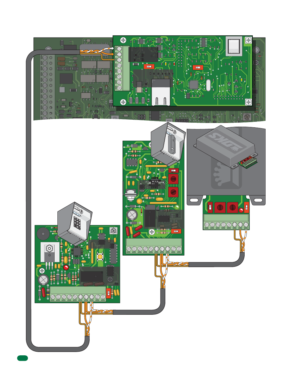
RS-485 Daisy Chain Wiring
RS-485
Keypad
RS-485
Cardreader
+
-
Com
Terminals 1 and 2
MUST be twisted.
Terminals 7 and 8
MUST be twisted.
Terminals 7 and 8
MUST be twisted.
Com
+
-
Com
+
-
Com
+
-
6 7 8
10
9
5
4
3
2
1
1
2
3
4
5
6
7
8
77
8
9
4
5
6
1
2
3
0
The wires connecting terminals 1 & 2 from
the 1812 Access Plus to terminals 8 & 7
on the DoorKing RS-485 boards MUST be
twisted. We recommend that you use
Cat5e cable for all the RS-485 connec-
tions (See page 12 for wire size and run
distances table). Use one twisted pair to
connect these terminals (terminal 1
connects to terminal 8; terminal 2
connects to terminal 7) and then one wire
from another twisted pair to connect the
common terminal (terminal 3 from the
1812 Access Plus to terminal 6 on the
RS-485 board).
If wiring will be
outdoors or under-
ground, use Cat5e
Gel Filled (flooded)
UV Resistant Direct
Burial Cable.
Any RS-485 Keypad, Cardreader and
MicroPlus RF Receiver sequence
allowed. Maximum distance from end
to end is 4000 feet in a Daisy Chain
format as shown, see next page for
different RS-485 wiring configurations.
Do Not power RS-485 devices from the 1812.
RS-485 devices must be powered from their
own power source. Refer to the individual device
wiring instructions for connection information
and wiring guidelines for these products.
Setting the device address switches
are different for each RS-485 device.
Refer to the individual RS-485
instruction sheet to set the addresses
for these products and see the next
page for more information about
address restrictions.
Cat5e
Cat5e
Cat5e
TERMINATION
RS-485 DATA A (+)
RS-485 DATA B (-)
RS-485 Common
6 7 8
10
9
5
4
3
2
1
6 7 8
5
4
3
2
1
RS-485
MicroPlus
RF Receiver
When 3 RS-485 wires are
connected to terminal, then
SW 5 termination switch
MUST be ON (End of chain).
2
354-01
0
When 6 RS-485 wires are
connected to terminal,
then SW1 termination
switch MUST be OFF.
1513-010
When 6 RS-485 wires are
connected to terminal,
then SW2 termination
switch MUST be OFF.
J1
RJ-45
LAN CONNECTION
O
AN
T
C
E
DATA
ATA
When 3 RS-485 wires are
connected to terminal,
then SW2 termination
switch MUST be ON.
OFF
80
53
-01
0
SW
4
SW
5
SW2
SW
3
ON
0
9
8
7
6
5
4
3
2
1
0
9
8
7
6
5
4
3
2
1
ON
Device Address
Set to 003
Device Address
Set to 004
Device Address
Set to 005