Dixon Valve 100 TON RAM SEC05 External Swaged Cam and Groove User Manual
Page 10
100 Ton Ram Instruction Manual
Cam & Groove Holedall Couplings
customer service
800
•
355
•
1991
8
Section 5
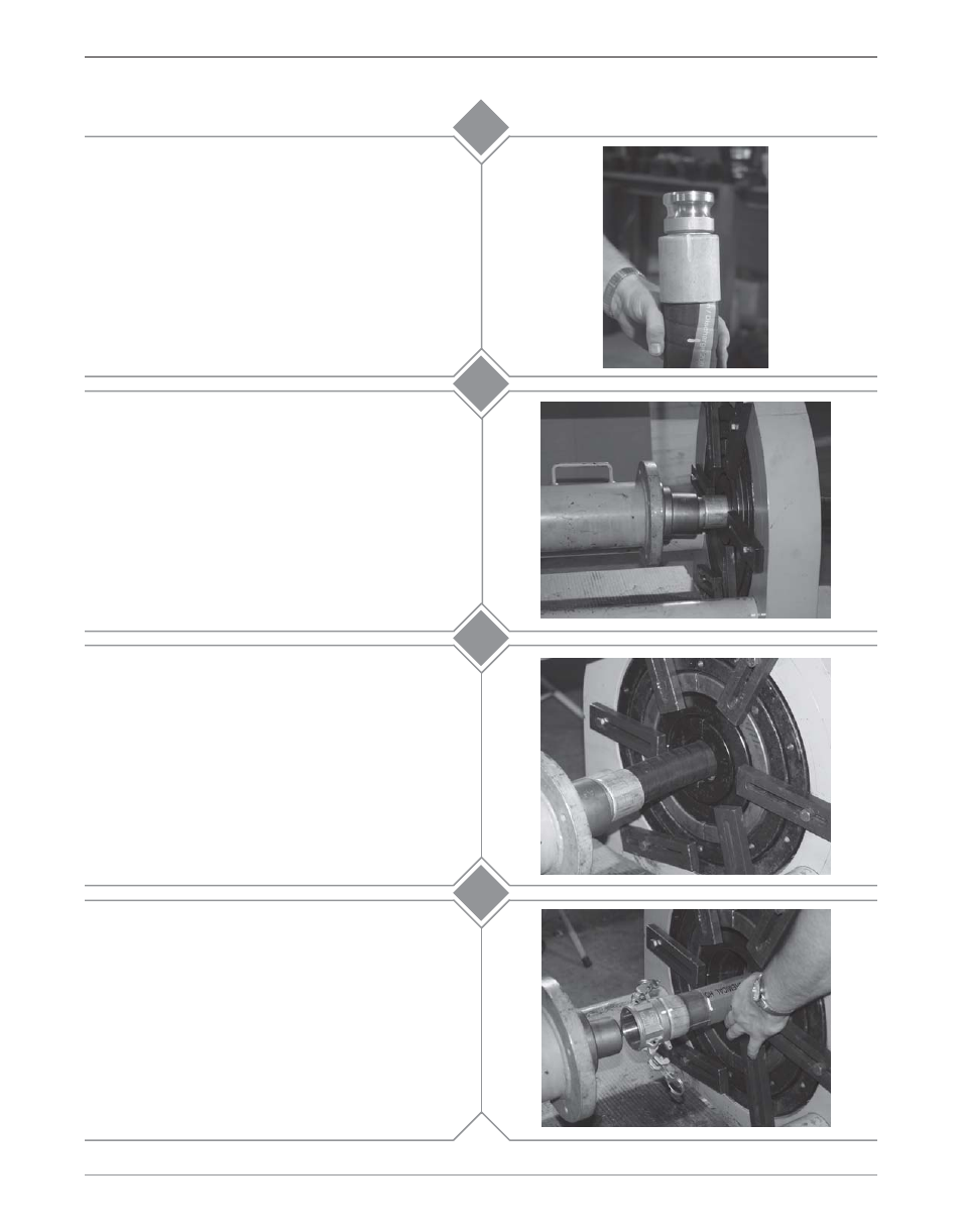
Check the ferrule for proper alignment. Ensure that
the mark on the ferrule (from Step 6b) is in the
center of the stem collar.
Move any tie down bars from the die that may come in
contact with the pusher. While holding the hose and
coupling up against the pusher, depress the button on
the remote. Once the ferrule has started to be reduced
(approximately 1/3 the way) it is no longer necessary for
the operator to hold the hose. Continue the swage until
the pusher contacts the die face. When this occurs,
release the button on the remote and move the
directional control lever to the “NEUTRAL” position.
Move the directional control lever to the
“FORWARD” position. Depress the button on the
remote and advance the cylinder until the end of the
ferrule is near the die opening. Using a wooden
board or metal pipe, lift the ferrule up. Jog the
cylinder by quickly depressing and releasing the
button on the remote. This will allow the ferrule to
enter the die slowly without contacting the die face.
Continue jogging the cylinder until the ferrule has
entered the die approximately 1-1/2"
Move the directional control lever to the “REVERSE”
position. Depress and hold the button on the remote
retracting the cylinder until there is sufficient room
for the stem and ferrule to clear the die bed.
For “E” style couplings:
Note: If the gauge reads 10,000 PSI before swaging
is complete, stop. The ferrule or die used for that
hose end may be incorrect. Contact Dixon for
further assistance.
13c
13d
13a
13b