Die change, 5111a crimping die chart – Dixon Valve 5111A Brass Ferrule Crimper User Manual
Page 3
Dixon, 800.355.1991
3
5111A_sales-413
DIE CHANGE:
1. Remove wing nuts No. 6 and lock washers No. 7. Die holder plate No. 3 can now be removed
exposing the crimping dies as well as the die holders No.10, links No. 11 and their pins
No’s 12 and 13.
2. Crimping dies will slide in and out of the mating dovetails freely.
3. All crimping dies are stamped with their part number. When the die holder plate is removed,
this number is visible on each die. When changing dies, be sure to install each die with the
numbered side facing the die holder plate. This is very important when using ribbed dies for
proper rib orientation.
5111A
CRIMPING
DIE CHART
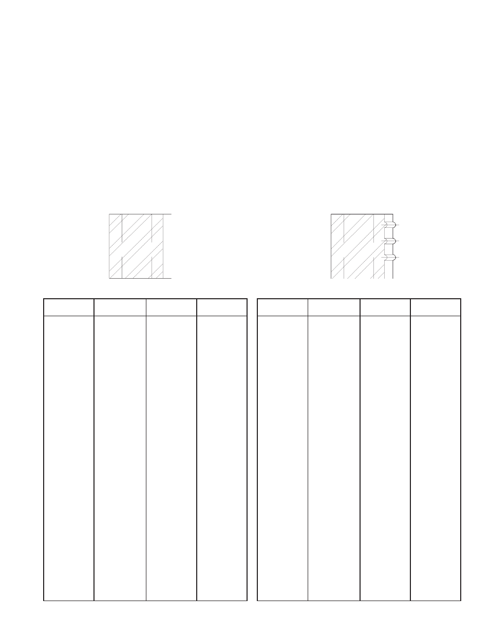
Plain Dies
P1
P2
P3
P4
P5
P6
P7
P8
P9
P10
P11
P12
P13
P14
P15
P16
P17
P18
P19
P20
P21
P22
P23
P24
P25
Die #
1.450
1.425
1.400
1.375
1.350
1.325
1.300
1.275
1.250
1.225
1.200
1.175
1.150
1.125
1.100
1.075
1.050
1.025
1.000
.975
.950
.925
.900
.875
.850
P26
P27
P28
P29
P30
P31
P32
P33
P34
P35
P36
P37
P38
P39
P40
P41
P42
P43
P44
P45
P46
P47
P48
P49
P50
.825
.800
.775
.750
.725
.700
.675
.650
.625
.600
.575
.550
.525
.500
.475
.450
.425
.400
.375
.350
.325
.300
.275
.250
.225
Bore
Die #
Bore
R1
R2
R3
R4
R5
R6
R7
R8
R9
R10
R11
R12
R13
R14
R15
R16
R17
R18
R19
R20
R21
R22
R23
R24
R25
Die #
1.450
1.425
1.400
1.375
1.350
1.325
1.300
1.275
1.250
1.225
1.200
1.175
1.150
1.125
1.100
1.075
1.050
1.025
1.000
.975
.950
.925
.900
.875
.850
R26
R27
R28
R29
R30
R31
R32
R33
R34
R35
R36
R37
R38
R39
R40
R41
R42
R43
R44
R45
R46
R47
R48
R49
R50
.825
.800
.775
.750
.725
.700
.675
.650
.625
.600
.575
.550
.525
.500
.475
.450
.425
.400
.375
.350
.325
.300
.275
.250
.225
Bore
Die #
Bore
Ribbed Dies