Warning, Wiring, Figure 2.1 • field wiring diagrams – Detroit Radiant Products Company DES3 Series User Manual
Page 7
WARNING
!
7
DES3
Series
2.0
Installation • Wiring
Wiring
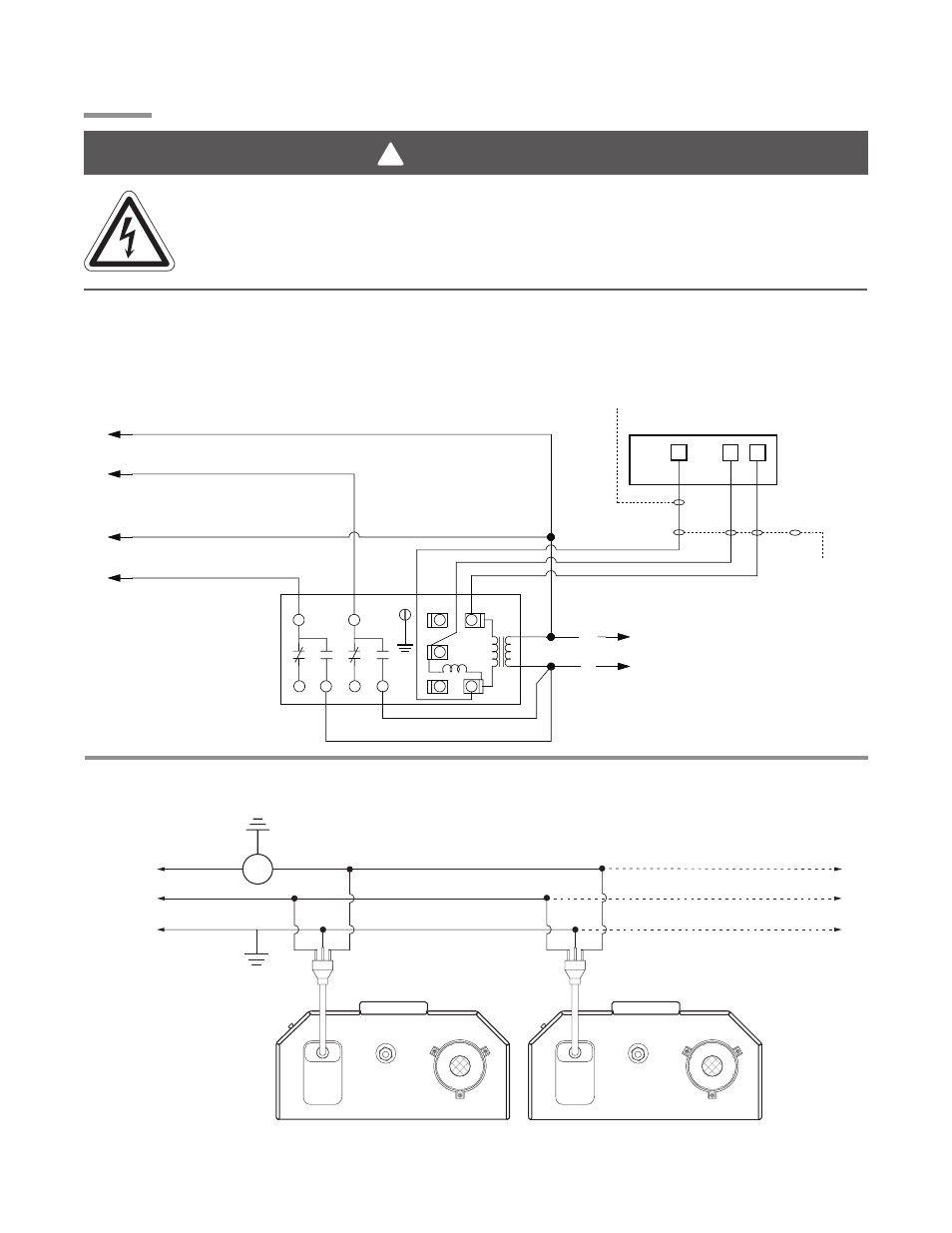
Figure 2.1
•
Field Wiring Diagrams
A. 24VAC Thermostat Control (requires optional combination relay transformer P/N: R8285B).
B. 120VAC Thermostat Connection(s).
120VAC-60 Hz.
Supply
NOTE: Up to 10 line voltage tube heaters
can be wired to 22 amp thermostat.
T
L1
Neutral
Ground
Heaters on the same vent
must
share the same thermostat.
Additional heaters
DES3 Burner Box
DES3 Burner Box
A transformer relay is
used in conjunction
with most low voltage
thermostats when
wiring tube heaters.
NOTE: The transformer relay
selected must be capable of
handling the combined
start-up amperage per relay
branch.
24VAC Thermostat
B
R
G
To Heater Branch #2
To Heater Branch #1
Pole
#2
Pole
#1
24VAC
115VAC
115VAC
115VAC
W
L1
N
White
White
Coil
W
G
Y
C
R
W
Common required for thermostats
that require constant power.
Field
Supplied
24VAC
Electric Shock
Field wiring to the tube heater must be connected and grounded in accordance with national,
state, provincial, local codes and to the guidelines in the Tube Heater General Manual and
Series Insert Manual. In the United States refer to the most current revisions to the ANSI/NFPA
70 Standard, and in Canada refer to the most current revisions to the CSA C22.1 Part I Standard.