Mityvac MV5545 FST PRO FUEL SYSTEM TESTER User Manual
Page 28
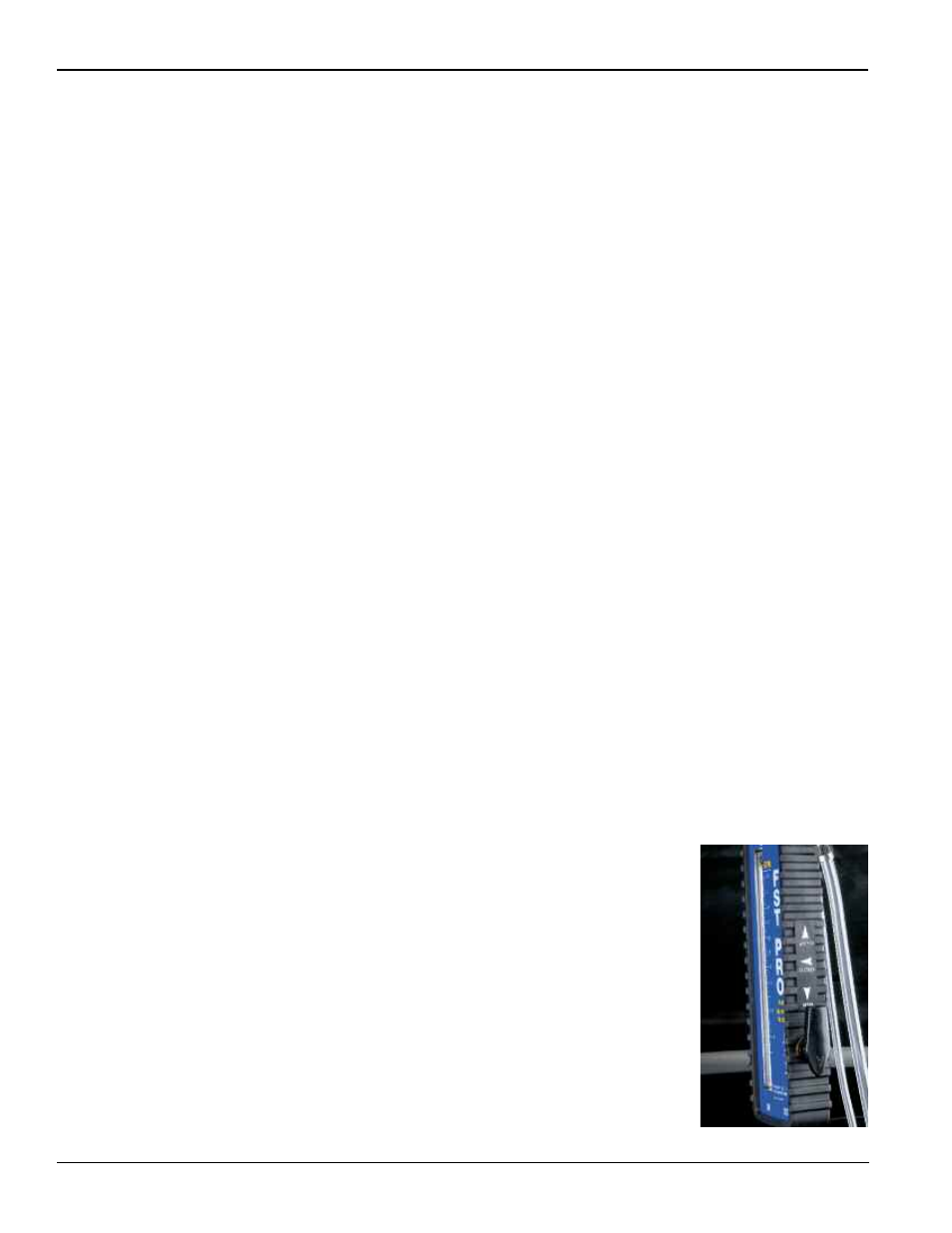
Fig. 50
A clogged inlet strainer can cause the fuel pump to cavitate because
it is starved for fuel. Cavitation will create rapid changes in fuel densi-
ty, causing the float in the FST flowmeter to bounce up and down
during the peak flow and/or capability test. It can also cause the nee-
dle on the pressure gauge to bounce. In addition, as the pump tries to
pull gas through the clogged strainer, it creates a pressure drop that
may cause air bubbles to form and become visible.
These indications of a clogged inlet strainer may or may not be evi-
dent during testing. If the results are inconclusive, and the fuel system
has an accessible inline filter, follow the procedure above to rule out a
clogged filter. If it is determined that the inline filter is not the problem,
replace the strainer or the pump module, and retest.
Over- or Under-restricting Pressure Regulator
Because mechanically regulated returnless fuel systems incorporate
the pressure regulator into the fuel pump module, it is not possible to
perform additional on-car testing to determine if the pressure regula-
tor is malfunctioning. If the pressure regulator and/or fuel pump is
replaceable within the module, the FST test results may be beneficial
in determining how to approach a repair.
Fuel Pump Malfunction
A malfunction at the fuel pump is typically indicated by a reduction in
both pressure and flow. At idle, the regulator may be able to maintain
pressure in the system, but the pressure will drop as soon as the
engine requires a greater volume of fuel. Performing flow demand and
capability tests should clearly indicate a pump problem.
If the FST indicates a pump is under performing, be sure to verify that
the vehicle does not use a multiple speed pump (see Fuel System
Components/Fuel Pumps). To properly test a fuel system with a multi-
ple speed pump, a scanner must be used to operate the pump at
high speed while the vehicle idles.
NOTE: Insufficient pressure and flow are an indication that a fuel
pump is under-performing, but do not necessarily mean that it is fail-
ing. Low voltage or a bad connection or ground will cause a pump to
under-perform, producing the same test results as if the pump were
bad. Before replacing any fuel pump based on the FST test results,
always follow the vehicle manufacturer’s recommended procedure for
testing all electrical connections and the electrical system charge. A
minor issue such as a loose ground can cause many problems that
resemble more serious malfunctions.
Returnless Fuel Delivery Systems
(Electronically Regulated)
At this point, it is assumed that the FST has been properly installed
inline with the fuel delivery system as recommended, and that it has
been primed to ensure no leaks are present (see FST Pro Setup and
Installation). The following procedure will ensure the most effective
diagnostic use of the FST:
Operational Test
1. Check the operating position of the flow control valve on the side
of the flowmeter to ensure the knob is in the OPEN position point-
ing down (Fig. 50). This will allow normal fuel system operation.
2. Start the car and allow it to idle.
Cranking or starting the engine should activate the ECM’s electric
fuel pump controls to turn on and run the fuel pump. If the fuel
pump does not operate, refer to the vehicle service information for
electrical diagnosis and repair of the fuel pump and associated
controls.
Page Number - 28
Form 824127