Mityvac MV5545 FST PRO FUEL SYSTEM TESTER User Manual
Page 23
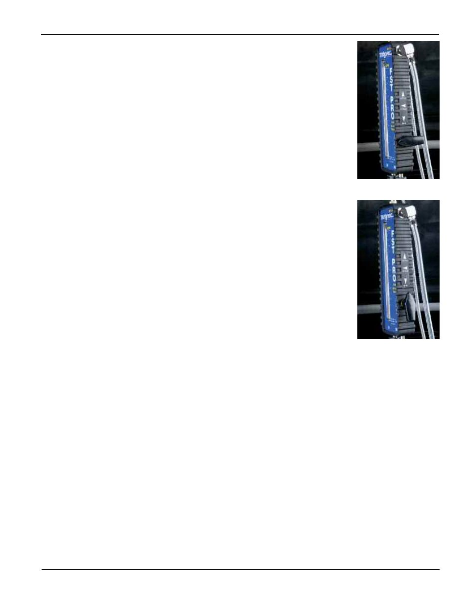
Fig. 42
Fig. 43
Form 824127
Page Number - 23
At idle, the volume of fuel flowing through the tester should remain
steady between 0.3 and 0.6 gallons per minute (GPM) or 1.1 and
2.2 liters per minute (LPM).
6. Noting the values for pressure and volume, if either is out of
range, these are indications of a problem with one or more com-
ponents of the fuel system. However, performing the Pressure and
Flow Demand Tests below, is required to reach a more accurate
diagnosis, and to pinpoint the cause of a malfunction.
Pressure Demand (Dead-head) Test
7. With the car idling, rotate the flow control valve on the side of the
flowmeter towards the 90° CLOSED position (Fig. 42).
Rotating the valve to CLOSED creates a restriction to the flow of
fuel through the tester. Watch the pressure gauge, as the valve is
rotated, the pressure should increase. Note the pressure when the
valve is fully closed. A good fuel pump should be capable of pro-
ducing pressure 50% to 100% higher than the rating of the fuel
system.
Caution: Never rotate the valve to the closed position for longer
than a brief instant. This is referred to as “dead-heading” the
pump, and can cause serious damage to the fuel system or
pump.
8. After noting the peak pressure, rotate the flow control valve back
to the OPEN position, and proceed to the flow demand test.
Flow Demand Test
9. With the car idling, rotate the flow control valve past the CLOSED
position to the BYPASS position pointing up (Fig. 43).
With the valve in the BYPASS position, the flow of fuel is routed
through the bypass port located above the valve, through the
bypass hose, and into the reservoir. All restriction to the flow of
fuel is removed. This allows the pump to output its maximum flow,
the value of which can be read on the flowmeter. The free flow
output of a typical fuel pump is between .7 and 1.0 GPM (2.5 and
4 LPM).
Note: Turning the valve to the full BYPASS position will prevent
fuel from flowing to the engine. If left in the BYPASS position for
too long, the engine will stall. If this happens, simply return the
valve to the OPEN position and restart the vehicle.
10. After noting the peak flow, return the flow control valve to the
OPEN position. Testing is complete.
Diagnosing the Results
The values for four critical fuel system performance indicators should
have been noted while following the procedures and performing the
tests outlined above:
•
Idle Pressure
•
Idle Flow
•
Peak (Dead-head) Pressure
•
Peak (Bypass) Flow
These indicators are the key to properly diagnosing a malfunctioning
fuel delivery system, and pinpointing the cause. In addition to these
values, note the vehicle’s engine size and maximum engine speed
(RPM). Refer to the Maximum Engine Fuel Volume Requirements
table (Appendix A), and use the size and speed values to determine
the maximum fuel volume requirement of the engine.
Refer to the Return Fuel System Diagnostic Guide (Appendix B). If
according to the chart, the FST test values indicate a normal operat-
ing fuel delivery system, then the engine is receiving the proper pres-
sure and flow of fuel, even under maximum load conditions. If the
FST indicates a normal operating fuel delivery system, yet the vehicle