Identifying fuel delivery systems – Mityvac MV5545 FST PRO FUEL SYSTEM TESTER User Manual
Page 16
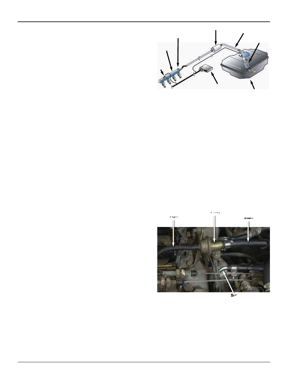
Fig. 27
Fig. 26
Page Number - 16
Form 824127
Electronically Regulated
Ford began developing an electronically regulated returnless fuel
delivery system in the late nineties, and began implementing it on
their cars in the early to mid-2000s. This system shares some of the
features and benefits of both return and returnless systems, but with
the addition of advanced control technology. The two main differ-
ences of an electronically regulated fuel system are the replacement
of the mechanical pressure regulator with an electronic pressure
sensor, and the introduction of a variable speed fuel pump (Fig. 26).
The fuel pressure sensor is mounted directly onto the fuel rail, which
ensures the most accurate reading of the pressure at the injectors.
The signal from the pressure sensor is fed to the ECM where it is
combined with other inputs such as from the O2 sensor. The ECM
processes the data and uses it to control the duty cycle of the
injectors and the speed of the fuel pump. Fuel pressure and volume
are controlled by the ECM speeding up or slowing down the fuel
pump. This eliminates the need for a pressure regulator.
Although a whole new level of technology and control has been
introduced with this system, the engine requirements are still the
same. The FST is just as effective at diagnosing an electronically
regulated system as a mechanical, and the test procedures are
just as straightforward.
Identifying Fuel Delivery Systems
Begin by opening the hood and locating the fuel rail. If the engine
has only one bank of cylinders, there will be only one fuel rail.
Engines with two cylinder banks will typically have two fuel rails,
each feeding the injectors in one of the banks. There will be a
crossover between the rails to allow fuel to flow from one side to
the other. Fuel rails vary in appearance from simple round tubes to
square or rectangular in shape.
Look for the fuel line(s). They typically come up from under the car at
the base of the firewall, run up the firewall, and then extend over to the
fuel rail(s). A return system will have two lines, one supplying fuel from
the tank, the second returning the unused fuel back to the tank. It is
easy to confuse fuel lines with lines for the evaporative system, so
inspect them closely. Fuel lines will be either steel or fuel rated rubber.
Return systems will have a pressure regulator typically mounted on
the end of the fuel rail, such that unused fuel flows out of the fuel rail,
through the pressure regulator, and into the return line. The pressure
regulator will typically have a vacuum line attached, which adjusts
fuel pressure regulation according to engine speed (Fig. 27). Some
cars will have a pulse dampener, which can be easily confused with
the regulator. The pulse damper is typically found on returnless
systems. It does not have a vacuum line attached to it, and is com-
monly mounted at the inlet, or extends from the side of the fuel rail.
Returnless fuel systems will have a single fuel line running to the fuel
rail. There will be no fuel pressure regulator located at the fuel rail.
Electronically controlled fuel systems will have a pressure transducer
mounted on the fuel rail (see Fuel System Components). The
transducer will have an obvious electrical connection with three
to five wires extending from it.
Pressure Test Port
Pressure
Sensor
Pump Module
ECM/PCM
Fuel Rail
Fuel Filter
Fuel
Tank
Fuel Supply Line
Pressure Regulator
To Manifold
Vacuum or
Atmosphere
Fuel Return Line
Fuel Supply Line