Principle of operation – Mityvac MV5545 FST PRO FUEL SYSTEM TESTER User Manual
Page 11
Form 824127
Page Number - 11
Principle of Operation
Fuel Delivery Basics
Modern fuel injected engines rely on precision fuel delivery to
perform at peak output and efficiency. It is the function of the
fuel delivery system to ensure that proper fuel pressure and
volume are present in the fuel rail to meet the demands of the
engine under varying operating conditions. When a fuel delivery
system is designed to meet a particular vehicle’s requirements,
a fuel pump is selected that can deliver at least the maximum
fuel pressure and volume requirement of the engine. Other
components of the fuel delivery system act upon the output of
the fuel pump to ensure the fuel pressure at the injectors is
maintained at the predetermined specification.
The maximum volume of fuel required by an engine varies
depending on its size. For example, an 8.0 liter engine running
at 3,000 rpm could consume as much as .34 gallons of fuel per
minute, while a 1.8 liter engine at the same speed would use
only .08 gallons per minute. When manufacturers design a fuel
delivery system for a specific engine, they consider the fuel
requirements based on the size, expected load and speed. This
data is used to program the vehicle’s Electronic Control Module
(ECM), which in turn controls the opening and closing (duty
cycle) of the fuel injectors. With the exception of emerging
electronically controlled fuel injection systems, the ECM
assumes that fuel pressure and volume to the engine are
maintained according to the designer’s specifications. If a
malfunction in the fuel delivery system such as a blocked filter,
faulty pressure regulator, or bad fuel pump, causes pressure or
flow to vary at the fuel rail, the ECM cannot directly sense this.
The only way the ECM can recognize a fuel related problem
exists, is through the O2 sensor in the exhaust. The O2 sensor
alerts the ECM if the exhaust mixture is rich or lean. The ECM
can only respond by opening the injectors for longer or shorter
time periods to inject more or less fuel. This may be enough to
mask small problems from the driver, but will result in poor fuel
efficiency. If the vehicle owner does not notice a decrease in
efficiency, and have the vehicle serviced, eventually the
malfunction will lead to greater drivability problems.
To help compensate for small fuel delivery problems such as a
partially clogged filter, manufacturers build a safety factor into the
fuel system so that it is capable of supplying somewhat greater
fuel pressure and volume than the engine will ever require.
Because of this, if a fuel delivery system is malfunctioning
enough to cause a noticeable drivability problem, with the
aid of the FST Pro, a technician should be able to accurately
diagnose and pinpoint the cause of the problem.
Application of the FST
The function of the FST Pro is to:
•
Inform technicians that there is a malfunction in the fuel
delivery system preventing the engine from receiving the
optimal fuel pressure and flow it requires to perform at peak
efficiency and performance.
•
Assist the technician in accurately pinpointing fuel delivery
system malfunctions, so as to obsolete current confusing,
time consuming, and costly troubleshooting procedures.
The FST is able to perform these functions by providing
real-time values for fuel pressure and flow, and by allowing
the technician to simulate varying load conditions on the engine
while the vehicle is idling in the shop. These functions are
performed by means of a pressure gauge, flow gauge
(flowmeter), and a patented flow control valve.
The FST operates by measuring and acting upon the flow of fuel
as it is pumped from the fuel tank to the engine by a vehicle’s
fuel delivery system. To accomplish this, the FST is designed to
be connected inline with the fuel system, such that fuel flows
normally through the tester just prior to entering the fuel rail.
It is critical that the FST be installed as close as possible to,
and directly inline with the fuel rail so that the pressure and
flow measurements most accurately represent the conditions
experienced by the engine. The further away from the fuel rail
that the tester is installed, the more likely the chance that an
external factor such as a blocked fuel line will affect the
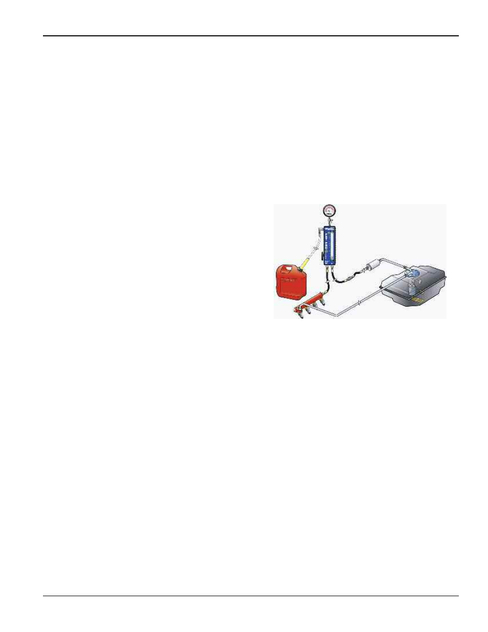
accuracy of the test results. Figure 17 illustrates a typical instal-
lation of the FST on a return type fuel delivery system.
NOTE: When conducting an initial evaluation of the fuel system
using the FST, never install it with any component such as a fuel
filter or pressure regulator located between it and the fuel rail.
Doing so will likely cause the readings to deviate from the pres-
sure and flow that the engine is experiencing, thus reducing the
accuracy and the reliability of the test results.
Diagnosing Fuel Delivery Systems
Upon proper installation of the FST and vehicle startup (see
Setup and Installation), the value for fuel pressure at idle will be
indicated on the pressure gauge, and the volume of fuel flowing
to the engine will be displayed by the flowmeter.
NOTE: While normal operating specifications for pressure and
flow will vary between vehicle makes, models, years and
engines, it is most likely that fuel pressure is the only one for
which a documented specification is available.
Regardless of the vehicle’s type of fuel delivery system
(see Modern Fuel Delivery Systems), the idle pressure can
immediately be noted and compared to the manufacturer’s
specification. However, the idle flow will vary significantly
depending on whether the fuel delivery system is return or
returnless. Assuming the fuel delivery system is operating
properly, the indicated flow of a return system will represent the
total volume the pump is capable of producing at the specified
pressure. On the other hand, the indicated flow of a returnless
system will represent only what the engine is using at idle.
Chances are this volume is so low, that it will not even register
on the flowmeter.
Fig. 17