Electronic installation – Max Machinery 234 Flow Meter User Manual
Page 7
( 7 )
234-000-350 © 2005 Max Machinery, Inc.
234-000-350 © 2005 Max Machinery, Inc.
( 7 )
Electronic Installation
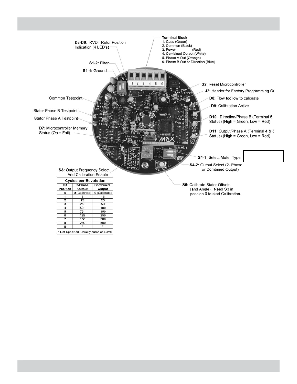
Microprocessor Reset:
S2: In the event that the tachometer does not appear to be operating correctly, resetting the microprocessor
by momentarily depressing S2 may solve the problem . While the reset button is depressed, the ‘MEM FAIL’
LED will turn on, and if the memory is good, the LED should turn back off when the button is released .
LVDT Rotor Position Indication LED’s:
D3-D6: These LED’s provide a graphical representation of the position of the LVDT slugs . This can be a
helpful troubleshooting aid when trying to determine if a meter is turning or not . The rotational pattern
observed on the LED’s corresponds directly to the speed of the LVDT slugs . At high speeds, the LED’s will just
look like they are blinking; the human eye can no longer discern the direction of motion . At very high speeds
the blinking will not even be obvious and they will all appear to be a constant brightness . At these higher
speeds, a divide-by-ten feature can be activated by pressing S5 (the ‘CAL’ button, make sure S3 is not in the 0
position, otherwise the calibration routine will be run!) . This only slows down the Rotor Position indication
LEDs, the output frequency does not change .
‘CAL’ LED:
D9: This LED changes color (red to green or green to red) 4 times per revolution while the microprocessor is
performing the calibration routine on the stator coils . When calibration is complete, it will turn off . See
Calibration Section for more information on calibration procedures
Due to the single sine wave
output of the LVDT encoder, the
resolution is 1/2 of the values
screenprinted on the PCB.
234 Series also
use 220/240
4.5-24