Mechanical installation – Max Machinery 234 Flow Meter User Manual
Page 4
Mechanical Installation
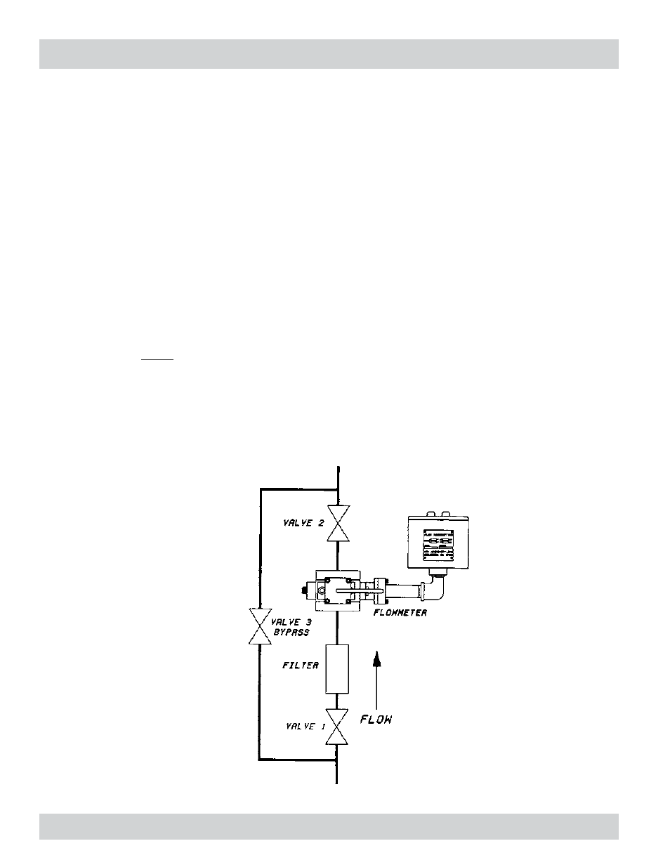
Orientation: The Model 234 is internally ported to allow air to be fully expelled from the meter provided the fluid
enters from the bottom (as shown below) . Air in the system can cause response delays and errors in measurement .
If the meter has to be mounted 90 degrees from what is shown, accuracy at low flows (less than flow rate in cc’s
x viscosity in centipoise = 200) may be affected . This is due to the weight of the piston assembly adding slightly
to the pressure drop required to lift the assembly during operation .
Line and Bypass Valves: These valves allow filter cleaning or flow meter removal without completely shutting
the system down and draining the lines . They also allow system start-up under conditions which could damage the
meter, such as air in the lines (which can overspeed the meter), high temperature conditions or initial line surges .
Filtration: The meter cannot tolerate contamination such as Teflon® tape, broken pipe threads, welding slag, sand
or other particulate matter . In general, a 10 micron filter is recommended, although in some applications finer
filtration may be worthwhile . If bidirectional flow is used, a filter should be installed on both sides of the flow
meter .
When the fluid contains large amounts of soft materials, it may pass through the meter satisfactorily but tend to
clog the filter . In this case, the filter may not be appropriate . A Max Sales or Technical Service Engineer can be
consulted for information regarding specific materials .
Clean Plumbing: Before installing the flow meter, clean the inside of the pipe line with compressed air or steam .
This is particularly important with new pipe .
Typical Installation
( 4 )
234-000-350 © 2005 Max Machinery, Inc.